Clutch control device and vehicle

a technology for controlling devices and clutches, applied in clutches, instruments, computing, etc., can solve problems such as user dislike of vehicle operation, fixed setting,

Active Publication Date: 2011-02-01
YAMAHA MOTOR CO LTD
View PDF79 Cites 3 Cited by
  • Summary
  • Abstract
  • Description
  • Claims
  • Application Information

AI Technical Summary

Benefits of technology

[0008]An aspect of the present invention involves the recognition that only a slight change in the target clutch position causes a significant change in the response, even without making any change to the control methods associated with the throttle valves. One reason for this is that the clutch rotational speed difference can be converged more quickly than before when the target clutch position is set closer to the engagement side than is conventionally done. For example, at a gear change, the half-clutch period is shortened and vehicle response is improved. Also, at the time of vehicle start-up, the rotational speed of the driven side of the clutch increases more rapidly. As a result, the vehicle speed increases at a higher rate and the vehicle's response is improved. In this manner, changing the target clutch position closer to the engagement side can reduce the period for a half-clutch state, which can improve response. An aspect of the present invention thus utilizes a chain of operations with a clutch control device to adjust vehicle responsiveness easily by artificially changing the target clutch position.
[0009]Another aspect of the present invention involves a clutch control device that can make adjustable response at vehicle start-up or at a shift change, and that allows easy or suitable clutch connection in accordance with user intentions.
[0011]With the clutch control device described above, a person can suitably tailor the responsiveness and abruptness of the vehicle's transmission operation to the operator's desire by changing the position of the friction clutch relative to the drive speed at least during clutch engagement. For example, the target position can be adjusted so as to advance the connection of the friction clutch when swift starting operation is desired, while the target position is adjusted so as to delay the connection of the friction clutch, thereby providing response that coincides with user intentions.

Problems solved by technology

However, some drivers are particular about their vehicle's responsiveness when the vehicle starts to run or is at a shift change, and may dislike the fixed setting.
For example, a user may dislike the operational feel of the vehicle when he or she does not obtain a response exactly as he or she desired, according to his or her operation of an accelerator.

Method used


Image

  • Clutch control device and vehicle
  • Clutch control device and vehicle
  • Clutch control device and vehicle

Examples


Embodiment Construction

[0027]Description is hereinafter made of the embodiments of the present invention in detail with reference to the drawings.

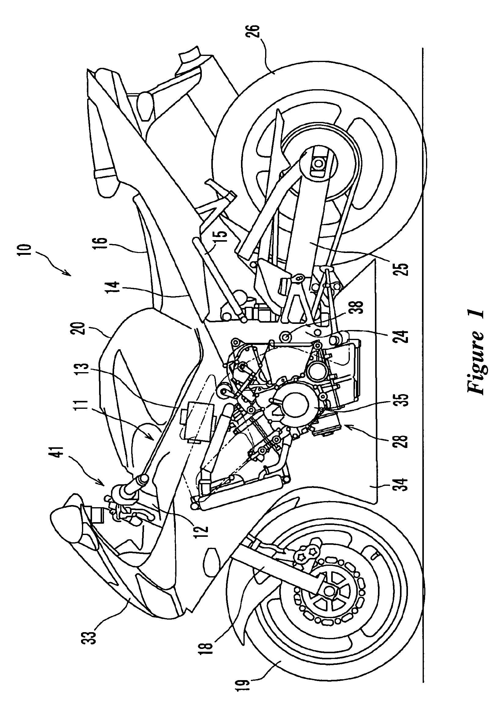
[0028]As shown in FIG. 1, the straddle-type vehicle according to this embodiment is a two-wheeled motor vehicle 10. The two-wheeled motor vehicle 10 has a body frame 11 which forms the skeleton thereof and a seat 16 on which a rider can be seated. As the rider seated on the seat 16, he or she straddles the body frame 11. The present clutch control device, however, is not limited to use with this particular type of vehicle. That is, the type of vehicle on which the present control device can be employed is not limited to the shape of the vehicle shown in FIG. 1, and the maximum speed, displacement and size of the vehicle also not limited. The straddle-type vehicle according to the present invention is not limited to a so-called motorcycle type two-wheeled motor vehicle having a fuel tank in front of the seat, and may be a two-wheeled motor vehicle of a different ...


PUM


Abstract

An EEPROM of an ECU (engine control unit) stores regulation maps corresponding to a plurality of running modes (e.g., normal mode, swift mode and gentle mode). The regulation maps regulate the relationship between the clutch rotational speed difference and the target clutch position. When any one of the running modes is selected according to user intentions, the target clutch position is uniformly changed according to the running mode.

Description

CROSS-REFERENCE TO RELATED APPLICATIONS[0001]The present application is based on and claims priority under 35 U.S.C. §119 to Japanese Patent Application No. 2006-114699, filed on Apr. 18, 2006; the entire contents of which is expressly incorporated by reference herein.BACKGROUND OF THE INVENTION[0002]1. Field of the Invention[0003]The present invention relates to a clutch control device for controlling an automatic clutch device, and to a vehicle incorporating the clutch control device.[0004]2. Description of the Related Art[0005]Prior vehicles have included an automatic clutch device for engaging and disengaging a friction clutch through an electric actuator. Such automatic clutch devices have often used a clutch position sensor for directly or indirectly detecting the position of the friction clutch (the distance between the friction plate and the clutch plate). For example, see Japanese Patent Publication No. JP-A-2002-067741.[0006]For use in the vehicles including the clutch pos...

Claims


Application Information

Patent Timeline
Patent Type & Authority Patents(United States)
IPC IPC(8): G06F7/00
CPCF16D48/06F16D2500/10412F16D2500/3026F16D2500/30406F16D2500/3067F16D2500/30806Y10T477/70F16D2500/7027F16D2500/70276F16D2500/7041F16D2500/70412F16D2500/70414F16D2500/70264
Inventor ZENNO, TOORU
Owner YAMAHA MOTOR CO LTD
Why Eureka
Try Eureka