Modular assembly

a technology of modular assembly and assembly frame, which is applied in the direction of amusements, transportation and packaging, wing accessories, etc., can solve the problems of difficult folding configuration transport, complex and tenuous transportation, and construction of building structures that can take weeks or months to construct, so as to facilitate the disposition of modular assembly and facilitate the positioning of the fram

Inactive Publication Date: 2011-02-08
MODULAR CONTAINER SOLUTIONS
View PDF42 Cites 58 Cited by
  • Summary
  • Abstract
  • Description
  • Claims
  • Application Information

AI Technical Summary

Benefits of technology

[0010]In order to facilitate the disposition of the modular assembly into either the building unit configuration or the shipping unit configuration an erection assembly is provided and selectively disposed in either a stored position or an operative position. The erection assembly comprises a plurality of erection members removable from their stored location within the frame and disposed exteriorly on the various portions of the frame. The erection assembly may also include a pulley and cable assembly cooperatively connected to the plurality of erection members, when in the operative position, to facilitate the positioning of the frame and or unit panels in either their closed or opened positions.

Problems solved by technology

These types of building structures can take weeks or months to construct, requiring many different types of materials and construction phases to complete.
The disadvantages include complex and tenuous transportation.
However, natural disasters and other catastrophes can destroy dwellings, thereby creating a need for fully equipped emergency shelters.
The disadvantages thus far to portable, foldable building units have been numerous: difficult to transport folded configurations; multiple loose panels, multiple unit sections, and difficult hinging and fastening mechanisms; difficult to assemble panels and elements; and a lack of utilities inside the unit.
Previous attempts at portable building units have also afforded hard-to-assemble structures that require special tools and sectional construction .

Method used


Image

  • Modular assembly
  • Modular assembly
  • Modular assembly

Examples


Embodiment Construction

[0035]It is to be understood at the outset that the present invention is susceptible of embodiment in different forms. Of course, there is shown in the drawings and will be described in detail herein at least one specific embodiment, with the understanding that the present disclosure is to be considered as an exemplification of the principles of the invention and is not intended to limit the invention to the embodiment or embodiments illustrated.

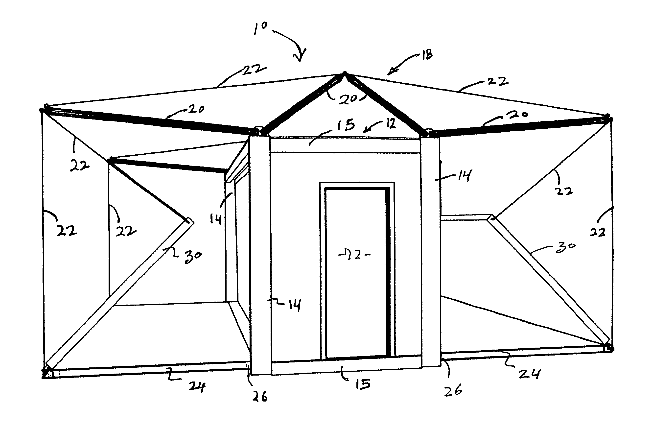
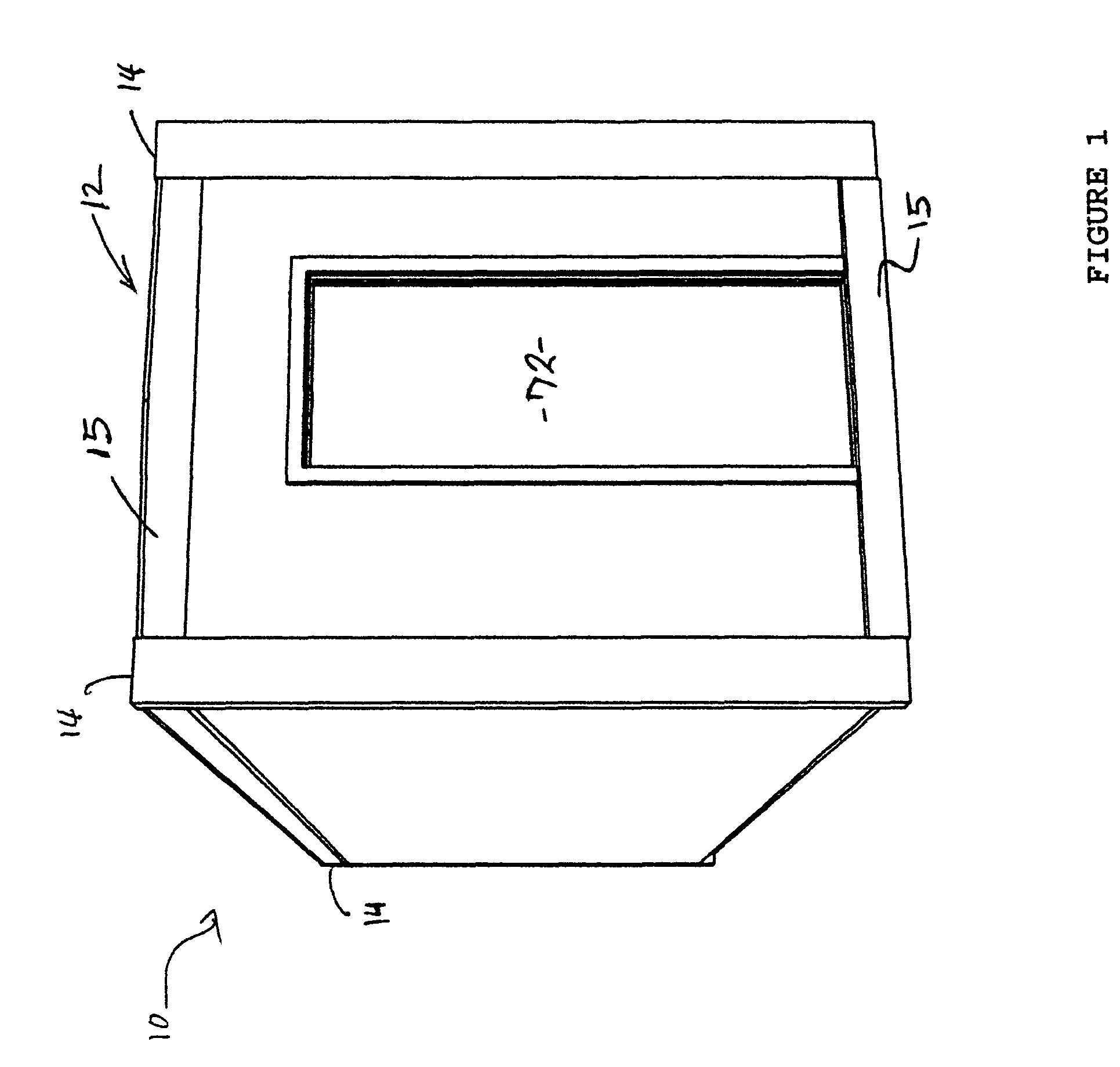
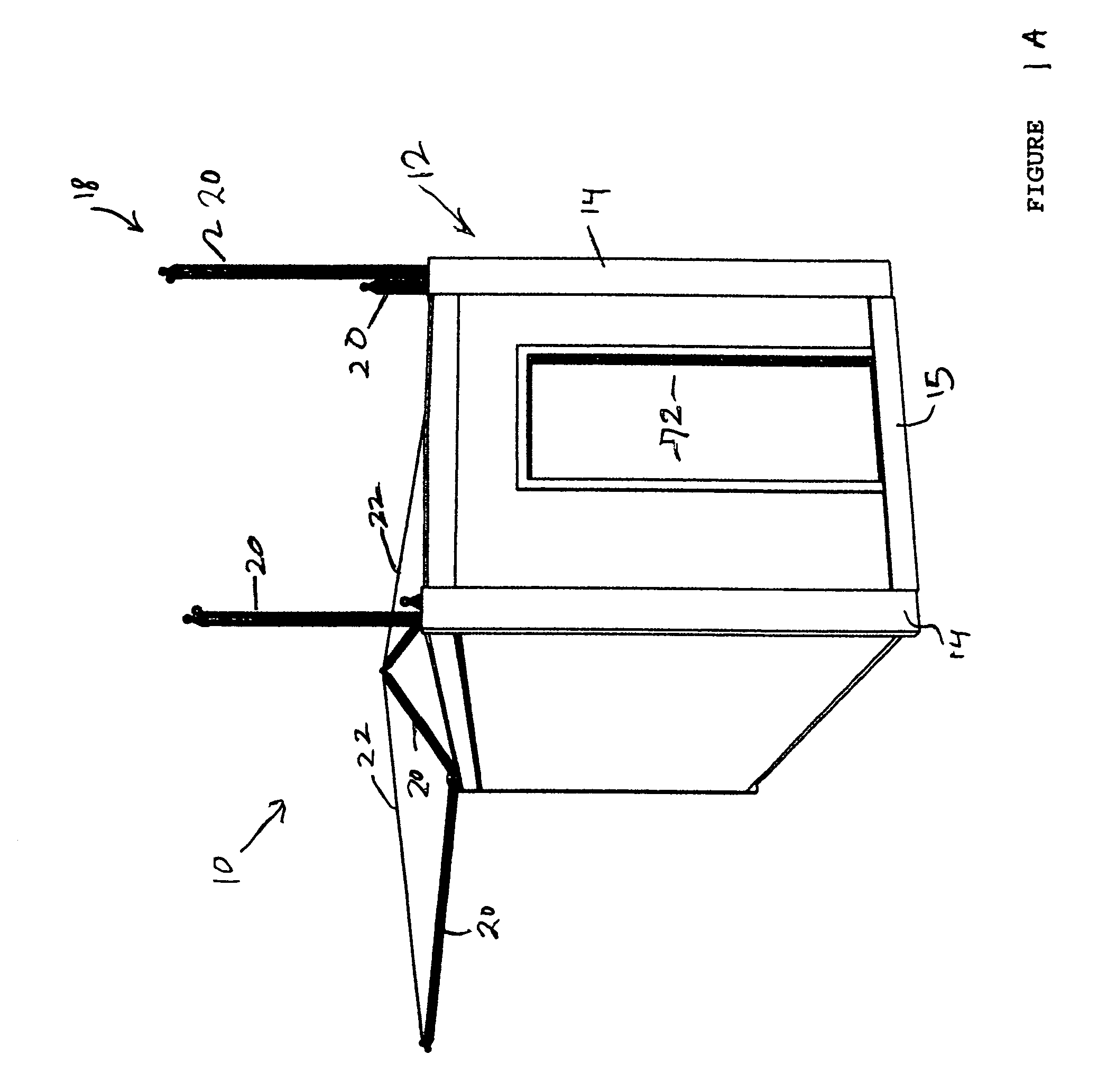
[0036]As shown in the accompanying FIGS. 1 through 14, the modular assembly of the present invention is generally indicated as 10 and is structured to assume either a shipping unit configuration as represented in FIG. 1 or an assembled building unit configuration as represented in FIGS. 10-14. When in the building unit configuration, the modular assembly 10 can be used either as a living unit, commercial unit, or other facilities, wherein one or more individuals can occupy the modular assembly 10 and perform any of a variety of different fun...


PUM


Abstract

A modular assembly structured to assume either a shipping container configuration or a building unit configuration including a frame comprising a plurality of support members and defining both a part of the building unit configuration and shipping unit configuration. A plurality of frame panels are movably connected to the frame and disposable in either a closed position or an opened position so as to respectively and at least partially define either the shipping unit configuration or the building unit configuration. The plurality of unit panels are movably connected to the frame and disposable outwardly therefrom to collectively define end wall portions and ceiling portions of the building unit configuration wherein the unit panels may be stored within the interior of the frame. An erection assembly is selectively disposable in an assembled position exteriorly of the frame and supported thereon so as to facilitate the assembly of at least some of the frame panels and / or unit panels.

Description

BACKGROUND OF THE INVENTION[0001]1. Field of the Invention[0002]This invention relates to a modular assembly capable of converting from a shipping container into a building unit with utility connections, and from a building unit into a shipping container. From the shipping container configuration, a plurality of frame and unit panels are selectively positioned to form the floor, walls, and ceiling of the building unit configuration thereby forming a living and / or commercial structure complete with electrical, water and sewage connections. The building unit can then also be folded and converted into the shipping container configuration for transport to and from various sites.[0003]2. Description of the Related Art[0004]Building units are an essential part of everyday life. Houses come in all shapes and sizes, and can be made in various ways from various types of materials. Traditionally, building units are constructed from the ground up in a specific location, for that location. Thes...

Claims


Application Information

Patent Timeline
Patent Type & Authority Patents(United States)
IPC IPC(8): E04B1/346E04H1/00B62D33/00E05C7/06A63G1/00
CPCE04B1/3444
Inventor GYORY, JANOS B.GYORY, ISTVAN
Owner MODULAR CONTAINER SOLUTIONS
Why Eureka
Try Eureka