Manual wrench for actuating cylindrical elements

a technology of wrenches and cylindrical elements, which is applied in the direction of wrenches, screwdrivers, manufacturing tools, etc., can solve the problems of increasing the complexity of the manufacture of such wrenches, the risk of accidental disassembly or breakage,

Active Publication Date: 2011-02-08
EGA MASTER
View PDF16 Cites 9 Cited by
  • Summary
  • Abstract
  • Description
  • Claims
  • Application Information

AI Technical Summary

Benefits of technology

[0012]Longitudinal incision is further provided in the mentioned toothed area of the fixed jaw by means of at least one groove dividing the teeth into partial sections, which favors the effect of attaching said teeth on the cylindrical elements actuated with the wrench, making the grip of the wrench on such cylindrical elements it is applied to more effective. An accessory element can further be incorporated in the dividing groove or grooves of the toothed section so as to adapt the use of the wrench for other types of cylindrical elements to be applied to.
[0013]The moving jaw additionally is equipped with side recesses in which the spring acting thereon is housed, which spring is arranged in the assembly such that it is completely housed in said recesses, without projecting outside, whereby preventing catches and blows from being able to affect the spring while the wrench is being used. Said spring is further incorporated in the assembly according to an arrangement which allows easy access to the securing points of the spring, whereby the assembly is very simple.

Problems solved by technology

The spring acting on the moving jaw is further arranged in those embodiments in a complicated assembly due to the difficulty of accessing the securing points of the spring inside the wrench, whereas in the solution in US 2003 / 0209109 the spring is biased on the mentioned moving jaw, being in a position in which during use of the wrench it may sustain catches and blows with the risk of the accidental disassembly or breakage.
In addition, the mentioned wrenches are provided with the ability to act on cylindrical elements having different diameters, requiring for the effectiveness the action that the teeth of the member act as perpendicular as possible on the element they are applied to, which is conventionally solved by providing the teeth of the member with different sizes and with different inclinations, combined with a shape of the part in which the toothed section is configured with successive arched areas having different radii, making the manufacture thereof even more complicated.

Method used


Image

  • Manual wrench for actuating cylindrical elements
  • Manual wrench for actuating cylindrical elements
  • Manual wrench for actuating cylindrical elements

Examples


Embodiment Construction

[0025]The object of the invention relates to a manual wrench manual for actuating cylindrical elements, such as pipes or the like, which due to its constructive and functional features is truly advantageous for this application.

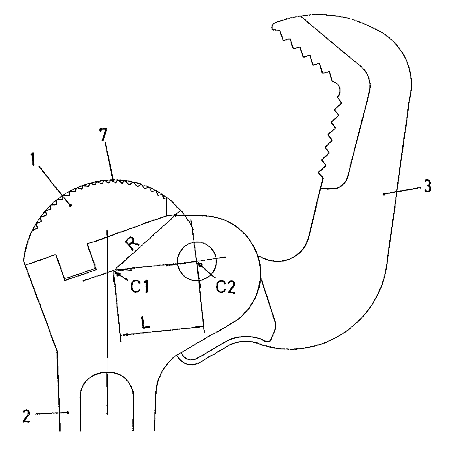
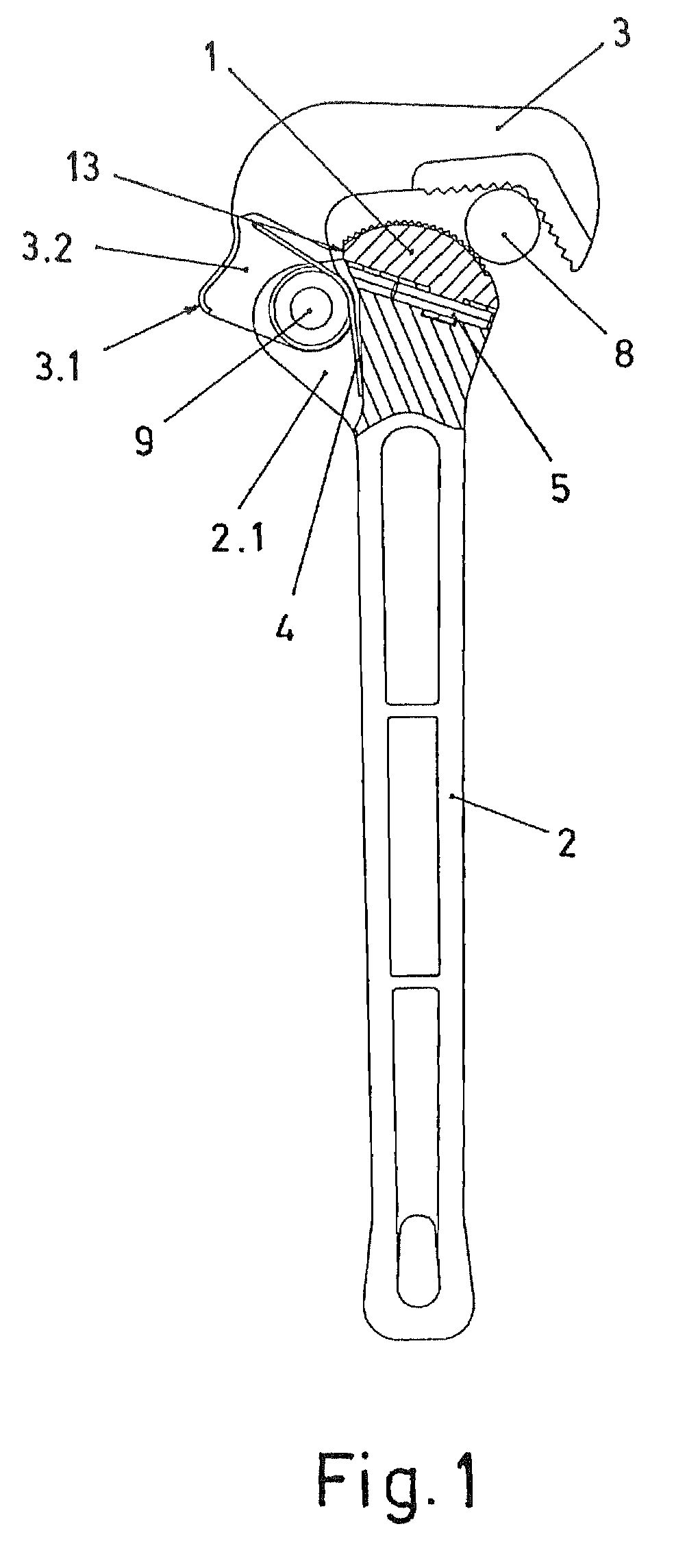
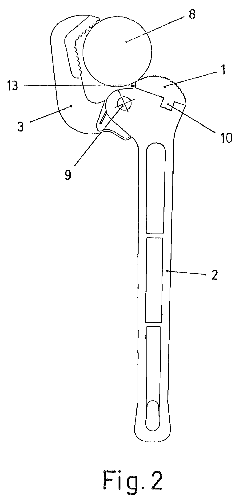
[0026]The proposed wrench consists of a fixed jaw (1) formed by a member coupled on the end of an actuating handle (2), and a moving jaw (3) articulated on the same end of the handle (2), including a spring (4) actuating the mentioned moving jaw (3) towards a closed position on the fixed jaw (1).

[0027]The securing of the fixed jaw (1) to the handle (2) is formed by means of a transverse keyed fitting securing the retention in the frontal direction, including a pin (5) traversing said keyed coupling, such that it prevents lateral shifting.

[0028]To that end, the member forming the fixed jaw (1) determines in the lower part, a key-shaped formation (10) introduced in the assembly in a housing (11) of the end of the handle (2), such that by means of the later inse...


PUM


Abstract

The invention relates to a manual wrench for actuating cylindrical elements. The inventive wrench comprises a fixed jaw (1) and a moving jaw (3) which are disposed on one end of a handle (2), whereby the fixed jaw (1) is secured with a transverse keyed assembly. The invention also includes an elastic pin (5) which extends through said keying. Moreover, the face of the fixed jaw (1) that faces the moving jaw (3) is equipped with a toothed section (7) comprising identical teeth which extend along a curved zone such as to define a single arc.

Description

FIELD OF THE INVENTION[0001]The present invention is related to quick-action wrenches used to actuate cylindrical elements, such as pipes or the like, proposing a wrench which, as a result of its constructive features, is truly advantageous for said function.STATE OF THE ART[0002]Wrenches for actuating cylindrical elements, referred to as quick wrenches, are known formed by a handle having at the upper part a fixed jaw and, articulated to the handle, a moving jaw which is actuated by a spring towards the closed position against the fixed jaw.[0003]Known solutions of said wrenches are, for example, the wrench of patent documents US 2003 / 0209109 and US 2002 / 0121162, in which the fixed jaw is formed by a toothed member coupled on the body of the handle by means of securing with screws, which requires the machining of boreholes and threads which increase manufacturing costs, as well as being a type of securing that can break.[0004]The spring acting on the moving jaw is further arranged ...

Claims


Application Information

Patent Timeline
Patent Type & Authority Patents(United States)
IPC IPC(8): B25B13/28
CPCB25B13/505B25B13/28
Inventor URQUIZU OSA, ANA
Owner EGA MASTER
Why Eureka
Try Eureka