
Motorcycle

a technology for motorcycles and crankshafts, applied in the direction of crankshaft transmission, friction roller based transmission, cycles, etc., can solve the problem of not being able to achieve the “gear-in” state during parking, and achieve the effect of safe extension

Inactive Publication Date: 2011-02-08
YAMAHA MOTOR CO LTD
View PDF12 Cites 4 Cited by
  • Summary
  • Abstract
  • Description
  • Claims
  • Application Information

AI Technical Summary

Benefits of technology

The present invention provides a motorcycle with a centrifugal clutch and a rotation suppression mechanism. The centrifugal clutch automatically engages and disengages based on the rotational speed of the drive source, reducing the burden on the rider during start-up and stopping procedures. The rotation suppression mechanism prevents the rear wheel from rotating when the drive source is stopped, improving parking safety. The motorcycle also includes a drive source, power transmission mechanism, gear shifts, handle, accelerator grip, brake levers, shift pedal, side stand, and rotation suppression mechanism. The technical effects of the invention include reducing the burden on the rider, improving parking safety, and enhancing the motorcycle's overall performance.

Problems solved by technology

Therefore, it is unnecessary to operate the clutch lever or the like during “start” and “stop” procedures.
In this case, however, even though the motorcycle is provided with the manual transmission mechanism, the “gear-in” state cannot be achieved during parking.
Therefore, in the motorcycle, the operation of the clutch lever during motorcycle “start” and “stop” procedures is unnecessary.

Method used


Image

  • Motorcycle
  • Motorcycle
  • Motorcycle

Examples


embodiment 1

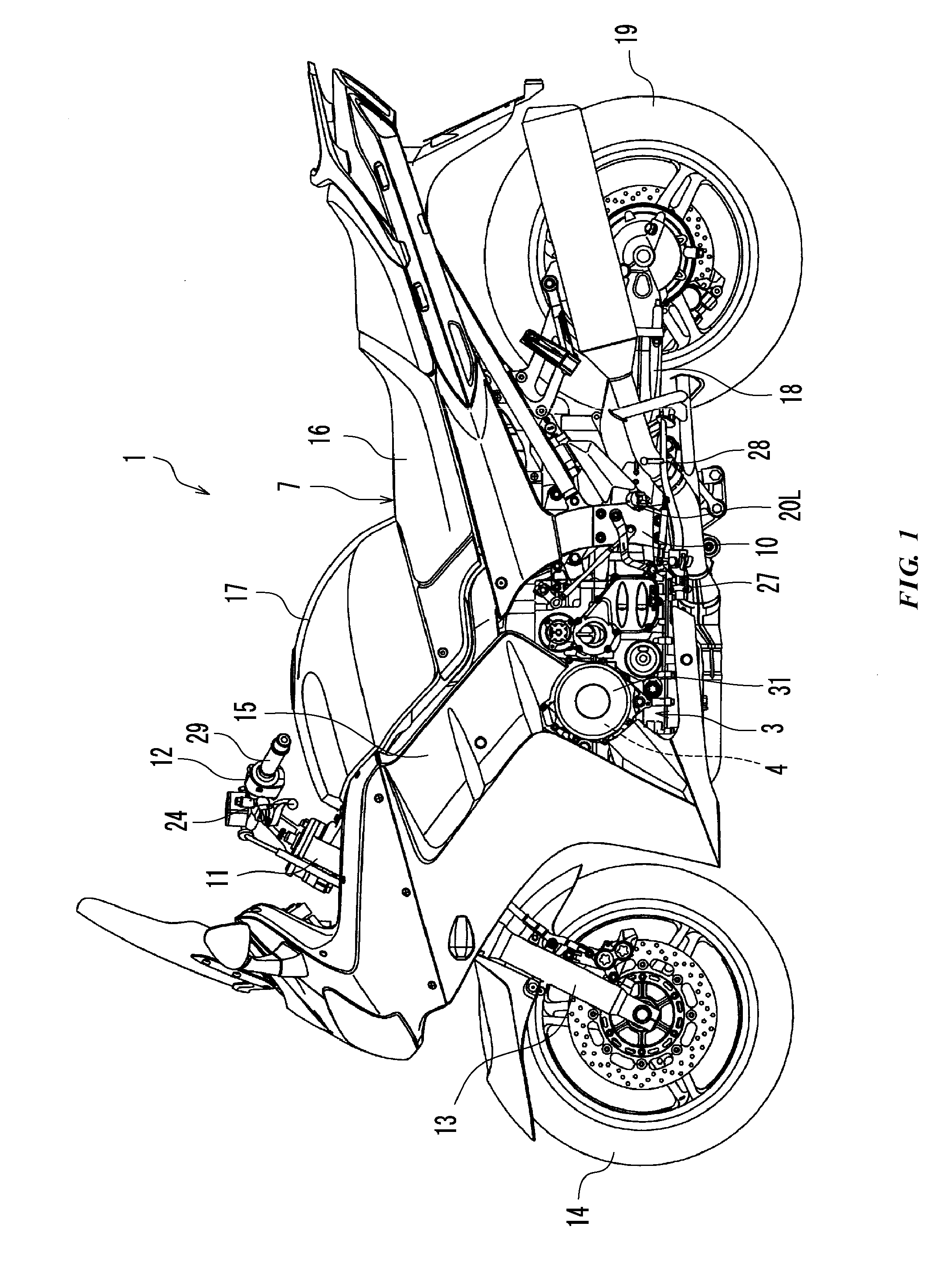
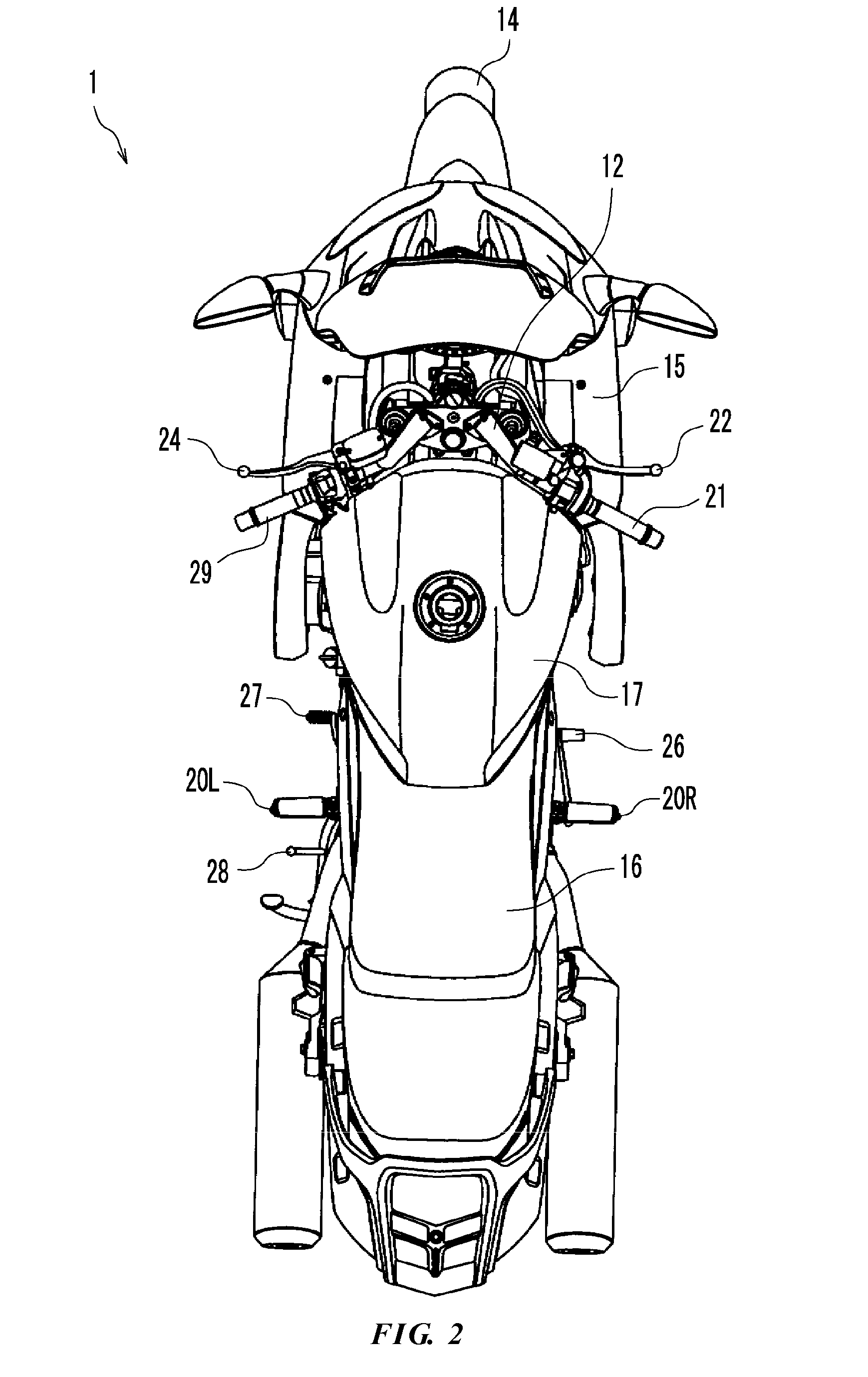
[0023]FIG. 1 is a left side view of motorcycle 1 according to a first embodiment. In the following description, the terms “front,”“back,”“left” and “right” refer to those directions viewed from the perspective of a rider occupying motorcycle seat 16 unless otherwise specified.

[0024]Schematic Constitution of Motorcycle 1

[0025]As shown in FIG. 1, the motorcycle 1 is provided with a vehicle body 7, a front wheel 14 provided on the front side of the vehicle body 7 and a rear wheel 19 provided on the rear side of the vehicle body 7. The vehicle body 7 is provided with a vehicle body frame 10. The vehicle body frame 10 has a head pipe 11. A handle 12 is attached to the upper end part of the head pipe 11. On the other hand, the front wheel 14 is rotatably attached to the lower end of the head pipe 11 via a front fork 13.

[0026]A power unit 3 is suspended on the vehicle body frame 10. A vehicle body cover 15 is attached to the vehicle body frame 10. At least a portion of the upper part of th...

embodiment 2

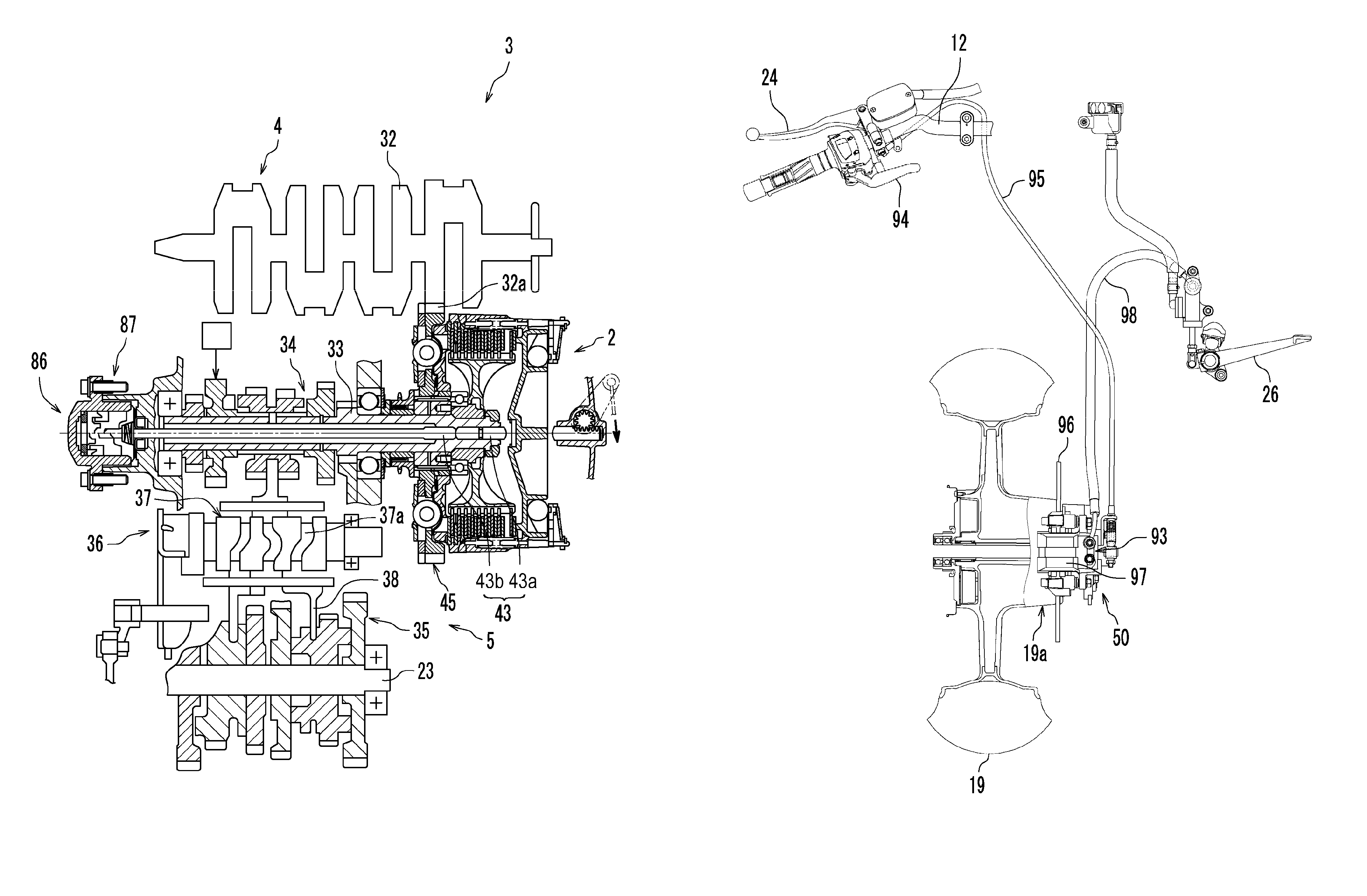
[0093]In the motorcycle 1 according to Embodiment 1, the rotation suppression mechanism 50 is provided with the pressing mechanism 55 for pressing the clutch 2 to achieve a connected state of the clutch 2. As shown in FIG. 8, a motorcycle 1 according to Embodiment 2 is provided with a rotation suppression mechanism 50 that includes a rear wheel brake 93 for braking the rear wheel 19 in place of the pressing mechanism 55 of Embodiment 1. The motorcycle 1 according to Embodiment 2 is provided with a switching member, such as switching lever 94, for switching between the operative state and inoperative state of the rear wheel brake 93, and a pipe 95 for connecting the rear wheel brake 93 to the switching lever 94. Since the remaining construction of motorcycle 1 is almost the same as that of Embodiment 1, the description of the remaining construction is omitted. Hereinafter, only the different construction from Embodiment 1 will be described in detail.

[0094]Embodiment 2 adopts a disk b...


PUM


Abstract

A motorcycle is provided with a vehicle body, front and rear wheels, an engine and a power transmission mechanism for connecting the engine to the rear wheel. A centrifugal clutch and a transmission having a plurality of gears are arranged in the power transmission mechanism. A handle is provided on the vehicle body. An accelerator grip is provided on the right side of the handle and a clutch lever is provided on the left side. A shift pedal for changing the transmission gear ratio of the transmission and a side stand are provided on the left side of the vehicle body. A rear brake pedal for braking the rear wheel is provided on the right side of the vehicle body. The motorcycle is also provided with a rotation suppression mechanism for suppressing the rotation of the rear wheel at least when the engine is stopped.

Description

PRIORITY INFORMATION[0001]This patent application is based on and claims priority under 35 U.S.C. §119 to Japanese Patent Application No. 2007-206170, filed on Aug. 8, 2007 and Japanese Patent Application No. 2007-278622, filed on Oct. 26, 2007, the entire contents of which are hereby expressly incorporated by reference.TECHNICAL FIELD[0002]The present invention relates to motorcycles.BACKGROUND ART[0003]Motorcycles provided with a so-called manual transmission mechanism have been known for some time. A motorcycle of this type is described, for example, in Japanese Patent No. 07-034916, published on Feb. 3, 1995. Generally, a motorcycle of this type is provided with an accelerator grip on the right side of a handle, a front brake lever on the right side of the handle, a clutch lever on the left side of the handle, a shift pedal disposed near a left side footstep, and a rear brake pedal disposed near a right side footstep. When a rider desires to shift gears, the rider grasps a clutc...

Claims


Application Information

Patent Timeline
Patent Type & Authority Patents(United States)
IPC IPC(8): B62D61/02
CPCF16D43/12
Inventor INOMORI, TOSHINORIISHIDA, YOUSUKE
Owner YAMAHA MOTOR CO LTD
Learn More