Power connection apparatus

a technology of power connection and connection arm, which is applied in the direction of coupling device connection, coupling device details, coupling/disengagement of coupling parts, etc., can solve the problems of terminal rusting, electrical leakage, and easy invading of the humidity generated in the chamber, so as to increase the length of the connection arm

Active Publication Date: 2011-02-08
SANYO ELECTRIC CO LTD
View PDF12 Cites 2 Cited by
  • Summary
  • Abstract
  • Description
  • Claims
  • Application Information

AI Technical Summary

Benefits of technology

In consequence, the abutment portion of the handle having the rotation angle regulated can abut on the power socket at an appropriate angle, and by the operation of pushing the power plug into the power socket in this state, the handle is rotated in the direction in which the grip portion comes close to the power socket, whereby the engaging claw can be engaged with the engagement portion, and connecting operation properties can be improved.
Moreover, the drip-proof cover comprises the connection arm extended with the elasticity and having the tip rotatably supported by the power socket, and the connection arm projects from the position different from the position where the line connecting the tip to the center of the drip-proof cover intersects with the drip-proof cover, and extends toward the tip thereof. Therefore, the length of the connection arm can further be increased in a limited space, and the length required during the attachment / detachment to / from the electrode portion or the holding portion can be achieved owing to the elasticity of the connection arm.

Problems solved by technology

On the other hand, when the power connection apparatus is provided on an back surface in the chamber which becomes a low temperature in the showcase, humidity generated in the chamber easily invades each connecting portion between the electrode portion and the terminal.
The invasion of the humidity causes electrical leakage or incurs the rusting of the terminals and the like.
Moreover, frost is generated between the power plug and the power socket, which causes a problem that with the growth of the frost, a force is applied in a direction in which the power plug is detached from the power socket, and the power plug drops down.
However, this obstructs the attachment / detachment operation of the power plug and the power socket.
Furthermore, in a low temperature environment, air in the power socket contracts, and accordingly, the attachment / detachment operation further becomes difficult.
Moreover, in the constitution, the handle can further rotate downwardly from substantially right angles with respect to the power socket, and hence when the end of the handle on the power socket side abuts on the power socket in a state where the handle is rotated downwardly on the front side owing to the own weight thereof, the abutment portion disturbs and disenables the operation of rotating the handle upwardly.
In consequence, after once rotating the handle upwardly, the power plug has to be inserted into the power socket while keeping the position of the handle, and a problem occurs that connecting operation properties become complicated.

Method used


Image

  • Power connection apparatus
  • Power connection apparatus
  • Power connection apparatus

Examples


Embodiment Construction

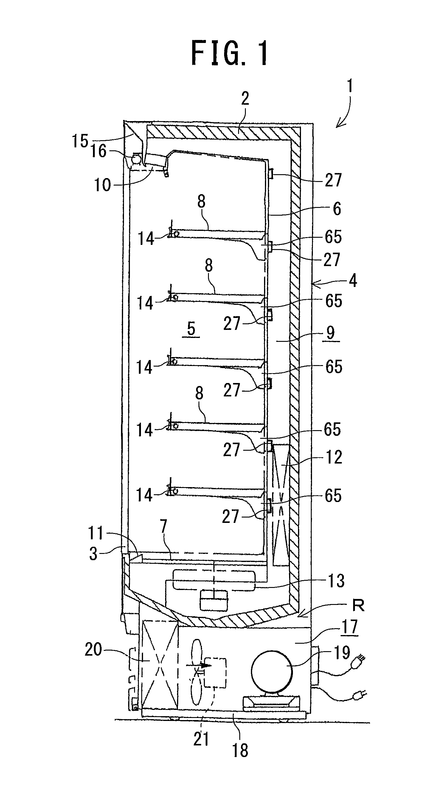
Hereinafter, a low temperature showcase 1 to which the present invention is applied will be described with reference to a schematic vertical side view of FIG. 1. The low temperature showcase 1 is installed in a store such as a supermarket or a convenience store, and side plates 3 and 3 are attached to both sides of an insulating wall 2 having a U-shaped cross section to constitute a main body 4. A partition plate 6 and a bottom plate 7 are attached inside the insulating wall 2 with a space therefrom, to constitute a display chamber 5 having an open front surface inside these components, and a series of cold air duct 9 is also interposed between these components and the insulating wall 2.

Furthermore, the duct 9 is connected to a discharge port 10 which opens at the upper edge of an opening of the display chamber 5 and to a suction port 11 which opens at the lower edge of the opening. Moreover, in the cold air duct 9 disposed along a back surface, a cooler 12 included in a cooling app...


PUM


Abstract

There is disclosed a power connection apparatus which can secure connection between a power socket and a power plug and which can simplify the connecting operation properties thereof. A handle rotatably attached to the power plug having terminals includes engaging claw disengageably engaged with engagement portion of the power socket having an electrode portion, an abutment portion which abuts on the power socket, and a grip portion. The rotation of the grip portion in such a direction as to come away from the power socket is limited by the angle of the rotation of the handle in a direction in which the grip portion comes close to the power socket.

Description

BACKGROUND OF THE INVENTIONThe present invention relates to a power connection apparatus for supplying a power to, for example, an illuminative lamp or the like in a showcase.In general, a showcase or the like is provided with a power connection apparatus constituted of a power socket connected into a chamber of a main body and a power plug plugged in this power socket to supply a power to an illuminative lamp or the like. In a conventional power connection apparatus disclosed in, for example, Japanese Patent Application Laid-Open No. 11-273775 (the patent document), a power socket is provided with a recess portion in which an electrode portion is disposed. This electrode portion is provided with plug-in ports for a power source. A power plug comprises a main body and a cylindrical portion connected to an illuminative lamp or the like via a wiring line, and terminals are provided on a bottom portion inside the cylindrical portion. In consequence, the power plug is plugged in the ele...

Claims


Application Information

Patent Timeline
Patent Type & Authority Patents(United States)
IPC IPC(8): H01R13/60
CPCH01R13/62933
Inventor OKETANI, TETSUYANAGATAKE, MASAHIKOISHIKAWA, SATOSHIMARU, KENJI
Owner SANYO ELECTRIC CO LTD
Why Eureka
Try Eureka