Intraocular lens

a technology of intraocular lens and lens front film, which is applied in the field of intraocular lens, can solve the problems of unsatisfactory adjusting function, poor vision quality, and lack of focus adjusting power of ocular function, and achieve the effect of effective focus adjusting power and efficient change of lens front film shap

Inactive Publication Date: 2011-02-08
KOWA CO LTD
View PDF27 Cites 496 Cited by
  • Summary
  • Abstract
  • Description
  • Claims
  • Application Information

AI Technical Summary

Benefits of technology

As will be apparent from the preceding description, in the intraocular lens of structure according to the present invention, pressure changes of the corpus vitreum in the eye can be utilized to efficiently bring about change in shape of the lens front film. Through changes of the curvature of the lens front film, it is possible to bring about change of the refractive power of the intraocular lens to achieve effective focus adjusting power.

Problems solved by technology

A resultant problem has been that while vision recovers after surgery, the ocular function lacks focus adjusting power.
However, since such intraocular lenses have simultaneous vision characteristics, quality of vision tends to be poor due, for example, to diminished contrast perception, so satisfactory adjusting function has not yet been achieved.
However, owing to the various pressures acting within the lens capsule, it is extremely difficult in practice to precisely control deformation of the balloon placed inside it, and hence to control changes in optical characteristics based on this deformation.
The resultant difficulty of ensuring basic vision and stable adjusting power makes the design impractical.
However, focus adjustment through deformation of the lens is premised on normal function of the lens capsule, the zonule of Zinn, the ciliary body, and so on, and it is difficult to imagine that the ciliary muscle will be able to exert sufficient force on the inserted intraocular lens subsequent to cataract surgery.
That is, even where contraction through tensing of the ciliary muscle is assumed, it is difficult to imagine that mere relaxation of the zonule of Zinn which connects the ciliary muscle and the crystalline lens will exert compressive force on the lens sufficient to induce curving deformation of the lens as described in Patent Citation 1.
With this intraocular lens as well, deformation of the elastic member occurs on the basis of deformation of the lens capsule, and thus as with the balloon discussed previously, there is the problem that it is difficult to control change in optical characteristics with high precision.
Furthermore, slight displacement of the optical lens in the anteroposterior direction will by itself produce a change in refractive power of at most no more than about 1 D, so sufficient adjustment function cannot be achieved.
However, the intraocular lens disclosed in this prior art publication is similar to Patent Citation 2 discussed earlier in that the optical lens merely undergoes slight displacement in the front-back direction, so sufficient adjustment function cannot be achieved.
Furthermore, after surgery the lens capsule contracts and fuses to the intraocular lens, and thus there is also a risk that movement of the optical lens will be inhibited by the lens capsule so that sufficient adjustment function is no longer achieved.

Method used


Image

  • Intraocular lens
  • Intraocular lens
  • Intraocular lens

Examples


first embodiment

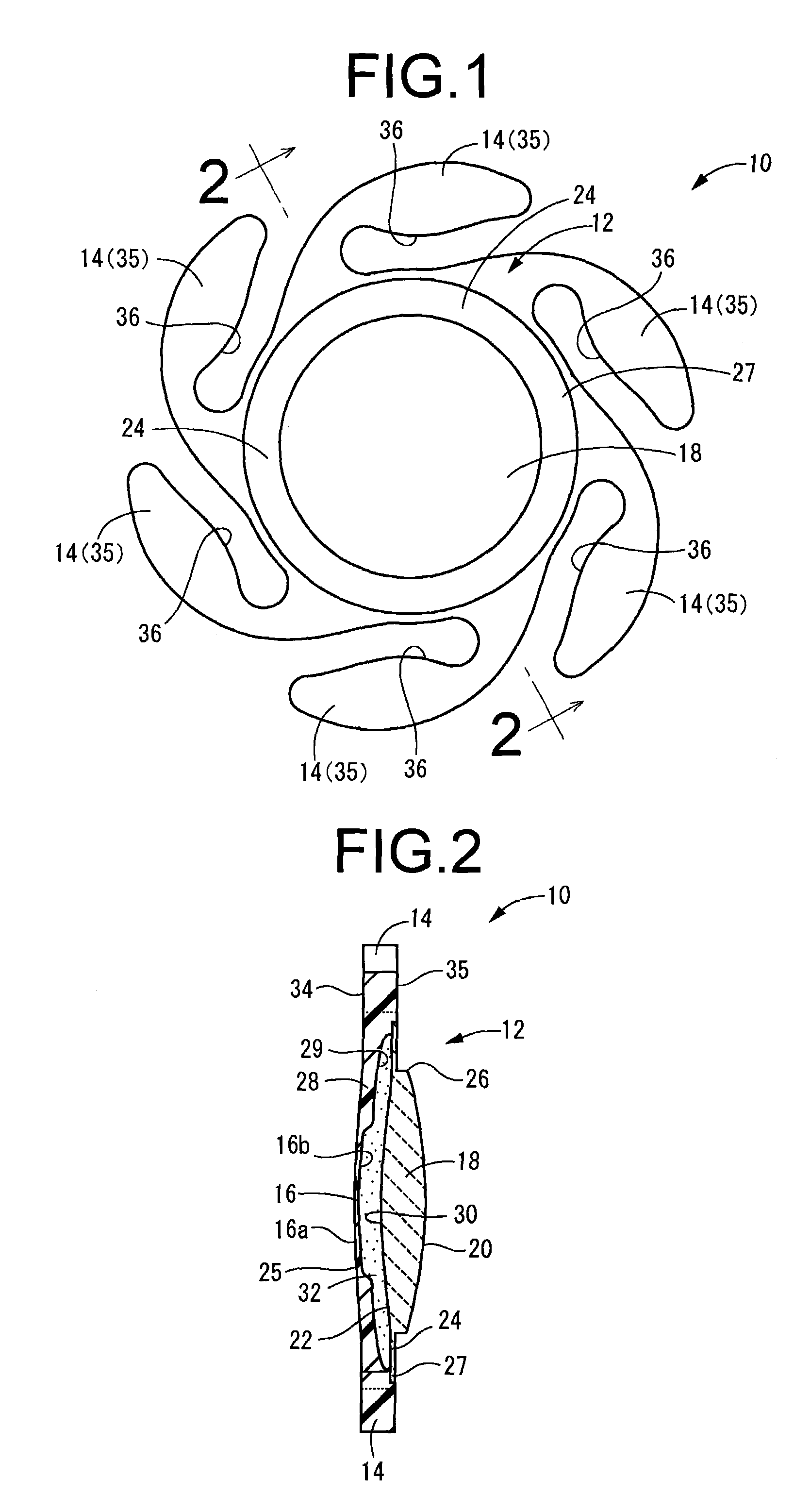
First, FIGS. 1 and 2 depict an intraocular lens 10 as the present invention. The intraocular lens 10 of this embodiment, when inserted into the lens capsule, will be positioned with the left side in FIG. 2 facing towards the cornea and with the right side facing the posterior capsule. In the description hereinbelow, “front side” will be used in reference to the left side in FIG. 2, and “rear side” will be used in reference to the right side in FIG. 2. FIG. 1 shows the back face (face lying toward the posterior capsule) of the intraocular lens 10. In FIG. 2, in order to facilitate understanding, the front film 16 and the rear film 24 are shown with exaggerated thickness dimensions.

The intraocular lens 10 has a structure in which a plurality (six in the present embodiment) of support leg portions 14 constituting the positioning portions are formed along the entire circumference of the outside peripheral section of an optical section 12 of capsule structure.

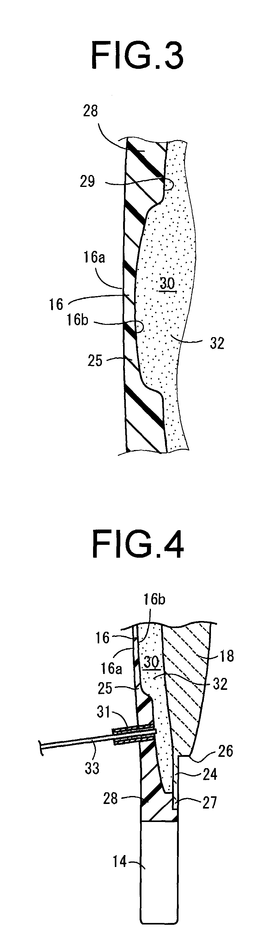
To describe in greater detai...

second embodiment

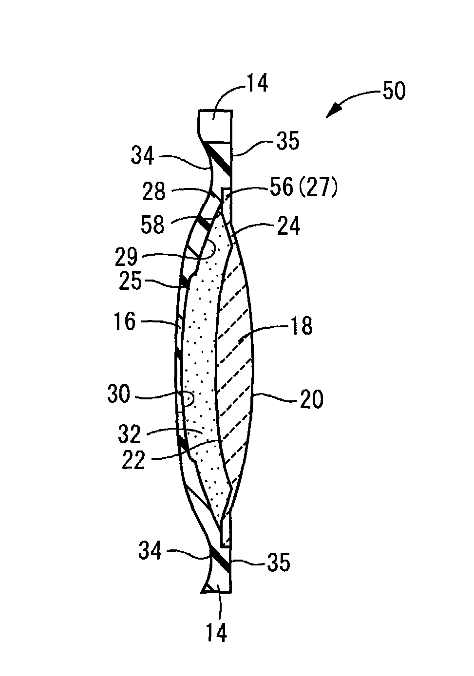
The intraocular lens 60 in the present embodiment is generally similar in shape of the intraocular lens 50 of the second embodiment described above, but has smaller thickness dimension in the anteroposterior direction due to the smaller volume of the internal space 30 in comparison with the intraocular lens 50. Since substantially the entire mounting edge portion 56 of the rear film 24 of the intraocular lens 60 is juxtaposed against the inner recess face 29, the internal space 30 of the present embodiment has a shape lacking a shoulder portion 58 in the intraocular lens 50 discussed earlier.

While the outer face 20 of the optical lens 18 in the intraocular lenses 50, 60 of the second and third embodiments above have flat shape lacking a sharp edge shape, it is of course possible for the outer face 20 of this optical lens 18 to be furnished with a sharp edge shape similar to that of the first embodiment described previously. An intraocular lens 70 having such a sharp edge face is sho...


PUM


Abstract

An intraocular lens of novel structure exhibiting an excellent focus adjusting power. A hollow capsule structure is filled with a transparent liquid-like or gel-like filler (32). A front wall of the capsule structure is composed of a flexible lens front film (16), and a rear wall of the capsule structure is composed of an optical lens (18) having a diameter larger than that of the flexible lens front film (16). Under a state inserted into and attached to a capsula lentis, pressure variation of a corpus vitreum acts on the optical lens (18) to enable focal refraction power to be adjusted by utilizing swelling deformation of the lens front film (16).

Description

This application is a U.S. National Phase Application of PCT International Application PCT / JP2006 / 318876 filed on Sep. 22, 2006, which is based on and claims priority from JP 2005-282748 filed on Sep. 28, 2005. The contents of these applications in their entirety are incorporated herein by reference.TECHNICAL FIELDThe present invention pertains to an intraocular lens for insertion into the lens capsule of the eye, and relates in particular to an intraocular lens having a focus adjusting function.BACKGROUND ARTIn the past, surgical techniques for cataracts and the like have employed a procedure in which the crystalline lens inside the capsule of the eye is extracted through an incision made in the ocular tissue of the cornea (sclera) or the anterior capsule of the lens, then inserting an intraocular lens which replaces the crystalline lens through the incision, to place it within the capsule.Intraocular lenses employed to date have been single focus lenses lacking a focus adjusting f...

Claims


Application Information

Patent Timeline
Patent Type & Authority Patents(United States)
IPC IPC(8): A61F2/16
CPCA61F2/1635A61F2/1648A61F2250/0018A61F2/16
Inventor NIWA, KAZUHARUKOBAYASHI, ATSUSHISATAKE, KOSUKE
Owner KOWA CO LTD
Why Eureka
Try Eureka