Camera and camera zoom control method

a technology of camera and control method, which is applied in the field of camera and camera zoom control method, can solve the problems of reducing the number of photographing images, imposing limits, and large so as to reduce the time difference between the timing of the photographing instruction and the timing of the actual photographing, and reduce the power consumption at the time of zooming.

Inactive Publication Date: 2011-02-08
FUJIFILM CORP
View PDF19 Cites 7 Cited by
  • Summary
  • Abstract
  • Description
  • Claims
  • Application Information

AI Technical Summary

Benefits of technology

[0015]The present invention has been made in order to solve the above-described problems, and provides a camera and a camera zoom control method that can reduce the power consumption at the time of zooming and shorten the time difference between the timing of the photographing instruction and the timing of the actual photographing.

Problems solved by technology

Therefore, there has been the problem that the power consumption is large.
In this manner, when the power consumption at the time of zooming is large, in a digital camera using a battery as the power source assuming use in a mobile environment, the problem arises that the number of photographing images is reduced due to the affect of the power consumed by the zoom motor.
In a digital camera that can execute various kinds of internal processing in a multitask manner with the purpose of speeding up the photographing speed, the problem arises that sometimes a limit must be imposed, due to the affect of the power consumed by the zoom motor, on the internal processing that can be executed in parallel.
Thus, there is no problem when the difference between the zoom magnifying power set by electronic zoom processing prior to photographing and the zoom magnifying power of the optical zoom set at the point in time of photographing is small, but when this difference is large, such as when the zoom magnifying power set by electronic zoom processing is the minimum zoom magnifying power and the zoom magnifying power of the optical zoom set at the time of photographing is the maximum zoom magnifying power, there is the problem that the time difference between the timing of the photographing instruction resulting from depressing the release button (the shutter) and the timing of the actual photographing becomes large.
When this time difference is large, not only does the feeling of operation at the time of photographing become uncomfortable for the user, but sometimes the precious opportunity to capture the subject at just the right time is missed, and this problem is serious.

Method used


Image

  • Camera and camera zoom control method
  • Camera and camera zoom control method
  • Camera and camera zoom control method

Examples


first embodiment

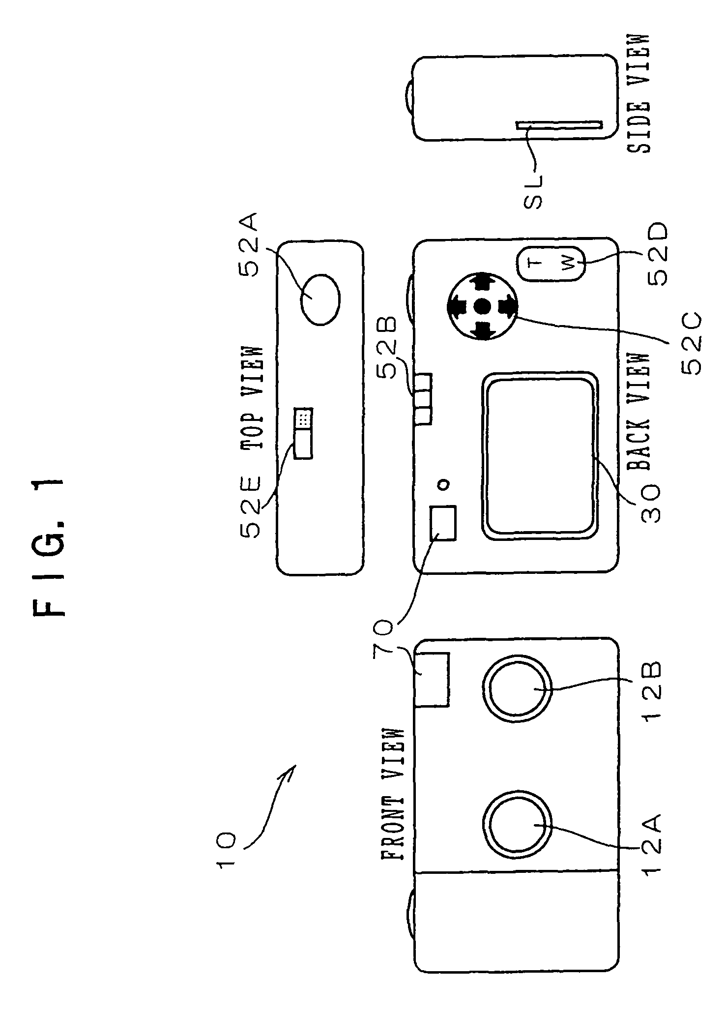
[0075]First, with reference to FIG. 1, the configuration of the exterior of a digital camera 10 pertaining to the present embodiment will be described. As shown in FIG. 1, the digital camera 10 includes a front surface provided with a pair of lenses 12A and 12B, which are for imaging a subject image, and a viewfinder 70, which is used in order to determine the composition of the subject to be shot.

[0076]The digital camera 10 also includes a top surface provided with a release button (shutter) 52A, which is depressed by the user when executing photographing, and a power switch 52E.

[0077]The release button 52A pertaining to the present embodiment is configured so that depression operations of two stages—one where the release button 52A is depressed to an intermediate position (described by “half-depressed” below) and one where the release button 52A is depressed to a final depressed position below the intermediate position (described by “fully depressed” below)—are detectable. Additio...

second embodiment

[0129]Next, a second embodiment of the invention will be described. Because the configuration of the digital camera pertaining to the second embodiment is the same as that of the digital camera 10 pertaining to the first embodiment, description here will be omitted.

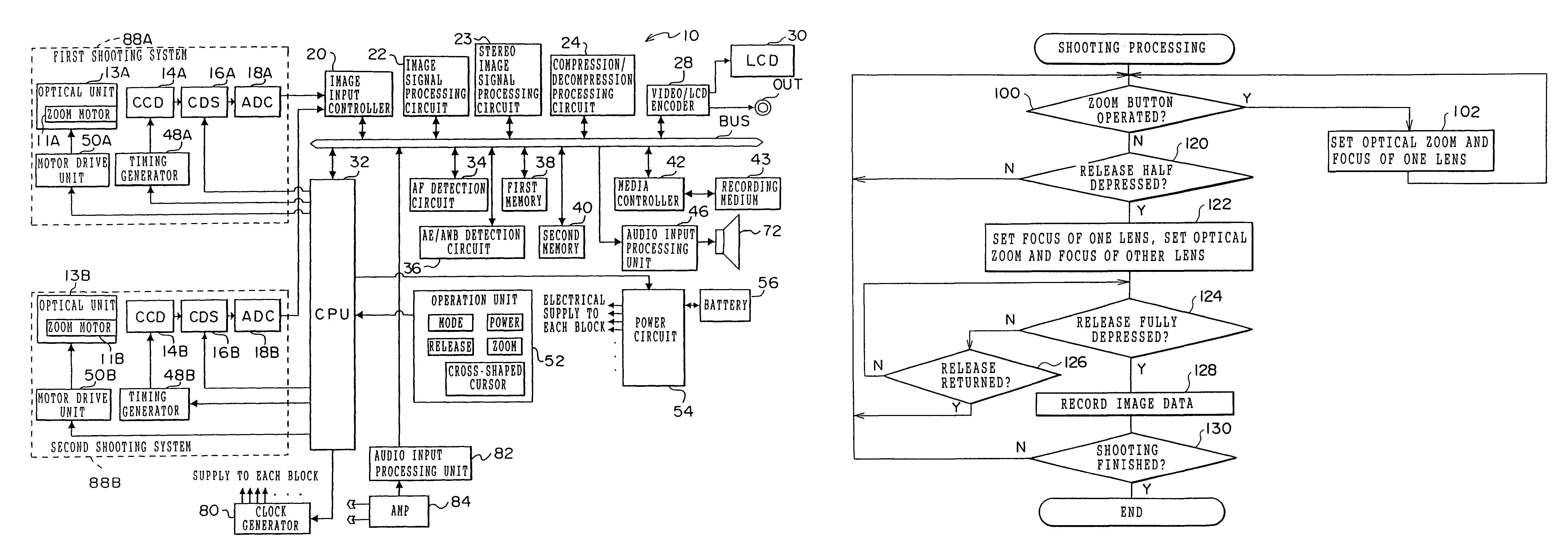
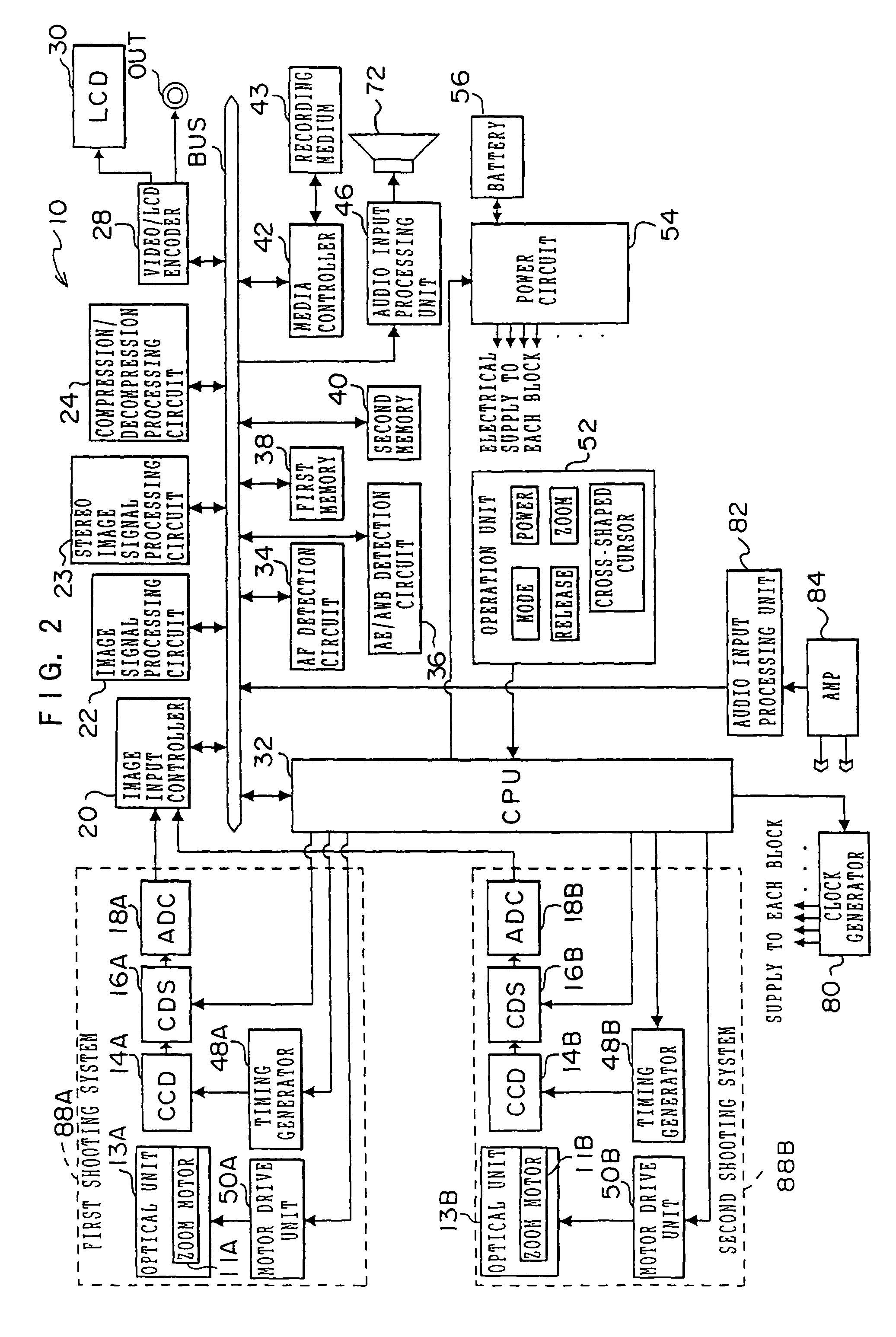
[0130]Processing of the portion relating particularly to the present invention of the processing executed in the digital camera 10 pertaining to the second embodiment at the time of stereo photographing will be described below with reference to FIG. 5 and FIGS. 6A and 6B. FIG. 5 is a flow chart showing the flow of the portion relating particularly to the present invention of the photographing processing executed by the CPU 32 of the digital camera 10 in the case where the stereo photographing mode has been set by the mode switching switch 52B. In FIG. 5, the same step numbers as those of FIG. 3 will be given to steps where processing that is the same as that of FIG. 3 is conducted, and description thereof will be omitted....

third embodiment

[0142]Next, a third embodiment of the invention will be described. Because the configuration of the digital camera pertaining to the third embodiment is the same as that of the digital camera 10 pertaining to the first embodiment, description here will be omitted.

[0143]Processing of the portion relating particularly to the present invention of the processing executed in the digital camera 10 pertaining to the third embodiment at the time of stereo photographing will be described below with reference to FIGS. 7 and 8. FIG. 7 is a flow chart showing the flow of the portion relating particularly to the present invention of the photographing processing executed by the CPU 32 of the digital camera 10 in the case where the stereo photographing mode has been set by the mode switching switch 52B. In FIG. 7, the same step numbers as those of FIG. 5 will be given to steps where processing that is the same as that of FIG. 5 is conducted, and description thereof will be omitted. Also, FIG. 8 is...


PUM


Abstract

The present invention provides a camera and a camera zoom control method that can reduce power consumption at the time of zooming and shorten the time difference between the timing of a photographing instruction and the timing of actual photographing. Until a release button is operated, the optical zoom magnifying power of a lens is controlled to become a zoom magnifying power corresponding to an operation with respect to a zoom switch, and when the release button has been operated, the optical zoom magnifying power of the lens is controlled to become the zoom magnifying power corresponding to the operation with respect to the zoom switch.

Description

CROSS-REFERENCE TO RELATED APPLICATION[0001]This application claims priority under 35 USC 119 from Japanese Patent Application No. 2003-419625 the disclosures of which are incorporated by reference herein.BACKGROUND OF THE INVENTION[0002]1. Field of the Invention[0003]The present invention relates to a camera and a camera zoom control method, and in particular to a camera and a camera zoom control method where plural lenses that image a subject image are disposed at respectively different positions and which can conduct stereo photographing using the plural lenses.[0004]2. Description of the Related Art[0005]In recent years, digital cameras, such as digital still cameras and digital video cameras, provided with both an optical zoom function and an electronic zoom function have become more common.[0006]Conventionally, in digital cameras of this type, from the standpoint of maintaining the quality of images (subject images) obtained by photographing, zooming in the range of the corres...

Claims


Application Information

Patent Timeline
Patent Type & Authority Patents(United States)
IPC IPC(8): H04N5/262H04N15/00H04N13/00H04N5/225H04N5/228H04N5/232G03B13/00G02B7/08G03B5/00G03B35/10H04N13/02
CPCG03B35/10H04N5/232H04N5/23241H04N5/23296H04N23/673H04N23/651H04N23/631H04N23/69
Inventor ISHII, AKIHIROUCHIOKE, KEIZO
Owner FUJIFILM CORP
Why Eureka
Try Eureka