Buffered mounting assembly with magnetic foot

a mounting assembly and magnetic foot technology, applied in the direction of fastening means, rod connections, weapons, etc., can solve the problems of affecting the underlying rail interface, and affecting the operation of the clamping foo

Active Publication Date: 2011-02-15
SWAN RICHARD E
View PDF26 Cites 32 Cited by
  • Summary
  • Abstract
  • Description
  • Claims
  • Application Information

AI Technical Summary

Benefits of technology

[0013]In this regard the present invention provides for an improved mounting assembly that is configured to be releasably attached to a standard dovetail rail profile. The mounting assembly of the present invention is particularly suited for use in connection with any firearm that utilizes a standard dovetail rail system. The mounting assembly is configured in the same manner as a traditional prior art mounting assemblies as pictured in FIGS. 3A and 3B. The mounting assembly includes a main body that has a lower portion that is configured to engage the dovetail rail found on most modern combat weapons as depicted at 12 in FIG. 1 and at 16 In FIG. 2 and an upper portion that can take a variety of configurations depending on the accessory that is to be mounted thereon. The lower portion of the mounting assembly has a first engagement member extending downwardly along one side thereof for engaging one side of the dovetail rail. A clamping assembly that includes a camming member having a foot and a shaft extending upwardly therefrom is installed into the main body opposite the engagement member and is received in a position adjacent the bottom of the mounting assembly body. An actuator arm is installed onto the top end of the shaft adjacent the top of the main body in a manner that engages the shaft and provides a means for the user to rotate the shaft and the foot such that the foot can be engaged and disengaged with the dovetail rail to hold the mounting assembly on the dovetail rail. In addition, a buffer pad is provided between the foot and the interface point on the dovetail rail to protect the rail from wear due to the clamping action.

Problems solved by technology

However, space on the upper receiver rail 12 is limited, and many military personnel often have multiple sighting devices that are each tailored to perform in different combat situations.
The difficulty is that there is simply not enough space on the integrated rail provided on the upper receiver to accommodate all of the desired accessories.
The difficulty with the prior art mounting assemblies is that the clamping surfaces that engage with the dovetail rail are necessarily formed from steel while the Weaver interfaces, receiver sleeves and upper receivers are generally made of aluminum or other light weight material.
Since these materials are softer than the steel used for the clamping surface, over time and after repeated use, the operation of the clamping foot scratches, cuts and erodes the underlying rail interface.
However, the inclusion of a buffer pad itself has also introduced a new set of difficulties in that when the mounting assembly is disengaged and the clamping foot is retracted, the buffer pad often remains in a downwardly depending position as can best be seen in FIG. 3B.
As a result, when installing a mounting assembly that includes a buffer pad, the device must be tilted in such a manner that the buffer pad is cleared out of the way, otherwise it interferes with installation of the mounting assembly onto the rail interface.

Method used


Image

  • Buffered mounting assembly with magnetic foot
  • Buffered mounting assembly with magnetic foot
  • Buffered mounting assembly with magnetic foot

Examples


Embodiment Construction

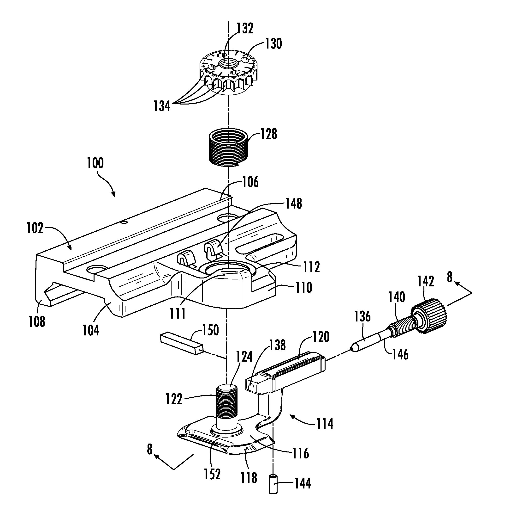
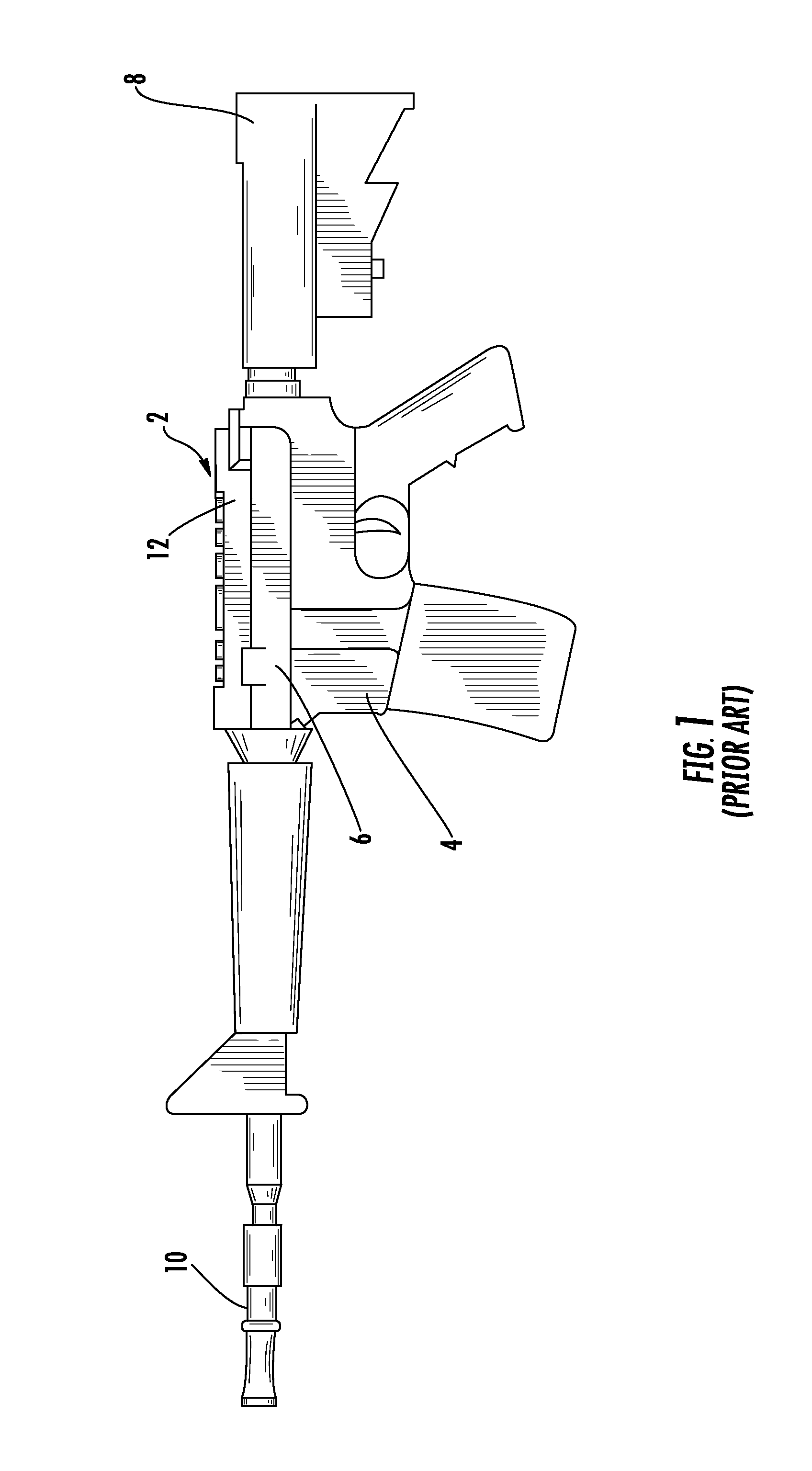
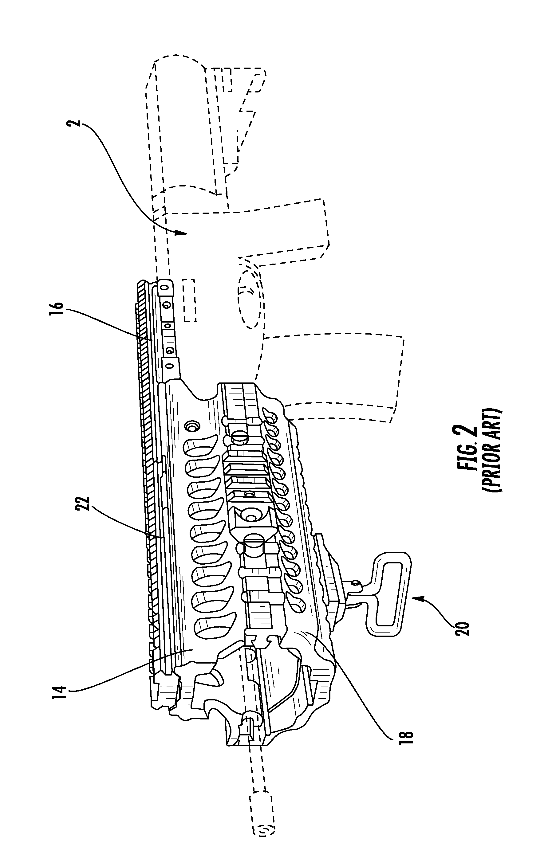
[0029]Now referring to the drawings, the mounting assembly of the present invention is shown and generally illustrated at 30 in FIGS. 4-6. The mounting assembly 30 is configured to be releasably attached to a standard dovetail rail profile as is depicted in FIGS. 1 and 2, and includes a means for withdrawing the clamping mechanism away from the dovetail rail when the clamping assembly is in the fully opened position. The mounting assembly 30 of the present invention is particularly suited for use in connection with any firearm that utilizes a standard dovetail rail system. Further, the mounting assembly 30 is configured in the same manner as a traditional prior art mounting interface devices. The mounting assembly 30 includes a lower clamping portion that engages the dovetail rail found on most modern combat weapons and an upper accessory interface portion that can take on a variety of configurations depending on the accessory that is to be mounted thereon.

[0030]Turning now to FIG. ...


PUM


Abstract

A mounting assembly for mounting accessories to a dovetail rail on a firearm is provided. The mounting assembly includes a main body having a lower portion with a first engagement member extending downwardly along one side thereof and a clamping assembly installed into the main body opposite the engagement member such that the clamping assembly can be engaged and disengaged with the dovetail rail to hold the mounting assembly on the dovetail rail. In addition, a buffer pad is provided between the clamping assembly and the interface point on the dovetail rail to protect the rail from wear. The clamping assembly includes a means for retracting the buffer pad when the clamping assembly is in the disengaged position, the retraction means preferably being magnetic. Such that the buffer pad is held out of the way when mounting or dismounting the mounting assembly.

Description

CROSS-REFERENCE TO RELATED APPLICATIONS[0001]This application is a continuation in part of U.S. patent application Ser. No. 11 / 829,587, filed Jul. 27, 2007, which is related to and claims priority from earlier filed U.S. Provisional Patent Application No. 60 / 820,659, filed Jul. 28, 2006.BACKGROUND OF THE INVENTION[0002]The present invention relates generally to accessory mounting assemblies for combat weapons such as the modular integrated accessory systems found on most modern combat weapons. More specifically, the present invention relates to an accessory mounting assembly that includes a buffer pad to prevent damage to the rail when the mounting assembly is engaged therewith, while also including a means for reliably retracting the buffer pad to facilitate dismounting when the mounting assembly is disengaged.[0003]As the field of combat and commercial weaponry expands, numerous add-on enhancements have become available for attachment to standard firearms, thereby significantly up...

Claims


Application Information

Patent Timeline
Patent Type & Authority Patents(United States)
IPC IPC(8): F41G1/38
CPCF41C27/00F41G11/003F41G1/387Y10T403/7071
Inventor SWAN, RICHARD E.
Owner SWAN RICHARD E
Why Eureka
Try Eureka