Method for operating a steam power plant, particularly a steam power plant in a power plant for generating at least electrical energy, and corresponding steam power plant

a technology of steam power plant and steam power plant, which is applied in the direction of steam engine plant, machine/engine, mechanical equipment, etc., can solve the problems of water loss from the water circuit and must be replenished, deionate which is drained off is not returned to the water circuit but is discarded, and the cost of deionate is significantly increased, so as to facilitate the overloading of the water treatment plant

Inactive Publication Date: 2011-02-15
SIEMENS AG
View PDF8 Cites 7 Cited by
  • Summary
  • Abstract
  • Description
  • Claims
  • Application Information

AI Technical Summary

Benefits of technology

[0007]The object of the invention is to eliminate the disadvantages of the prior art. Specifically the object of the invention is therefore to reduce significantly the running costs of a steam power plant, and of a power plant for generating electrical energy using such a steam power plant, which result from deionate provision. A further object of the invention is to reduce significantly the environmental impact of waste water and the consumption of water. It is likewise the object of the invention to shorten the startup time of the steam power plant with minimal cost / complexity.
[0009]The invention has the advantage compared to the prior art that the costs of providing deionate, particularly in the event of frequent startups and shutdowns, are markedly reduced. Using the invention it is additionally possible to operate steam power plants even in regions with a severe water shortage. In addition, the invention enables a large amount of water to be saved and the environment is less impacted by discharged waste water. The startup time of the steam power plant or of the power plant is shortened. In particular, this is achieved by recycling essentially all the drained water, which essentially means, for example, that about 99% of the drained water is fed back into the system.
[0011]In an advantageous embodiment of the invention the drained water is collected, stored and completely fed back to the water circuit at least from the pressure stage with the highest pressure. Thus the largest part of the drained water can be fed back in a simple manner with little expense, as the amount of water flowing in the highest pressure stage constitutes the largest part of the water in the entire water circuit.
[0012]In addition to the highest pressure stage, at least one other pressure stage whose pressure level is lower than that of the highest pressure stage can be advantageously included, all the pressure stages also being able to be included in a corresponding embodiment. In this way a larger part or all of the drained water is collected, stored and fed back to the water circuit, thus saving even more water.
[0013]In a further advantageous embodiment of the invention, the drained water undergoes liquid water / steam separation, it being possible for the separated steam to be fed to the condenser of the steam power plant, thereby enabling the separated clean steam to be easily cooled and liquefied in the condenser. This largely eliminates the need for special cooling of the stored water. It also provides a simple means of feeding the collected water back into the water circuit.

Problems solved by technology

This means that water is lost from the water circuit and must be replenished by supplying additional water known as deionate.
The disadvantage with the prior art is in particular that the expensively produced deionate which is drained off is not returned to the water circuit but is discarded to the environment in the form of waste water.
With conventional steam power plants, the deionate costs incurred are significantly increased, particularly in the event of frequent startups and shutdowns.
Moreover, the environment is considerably impacted by the heavy waste water discharge.
The re-supplied deionate has a high oxygen and carbon dioxide content requiring deaeration of the deionate, which means a longer startup time for the steam power plant.

Method used


Image

  • Method for operating a steam power plant, particularly a steam power plant in a power plant for generating at least electrical energy, and corresponding steam power plant
  • Method for operating a steam power plant, particularly a steam power plant in a power plant for generating at least electrical energy, and corresponding steam power plant

Examples


Embodiment Construction

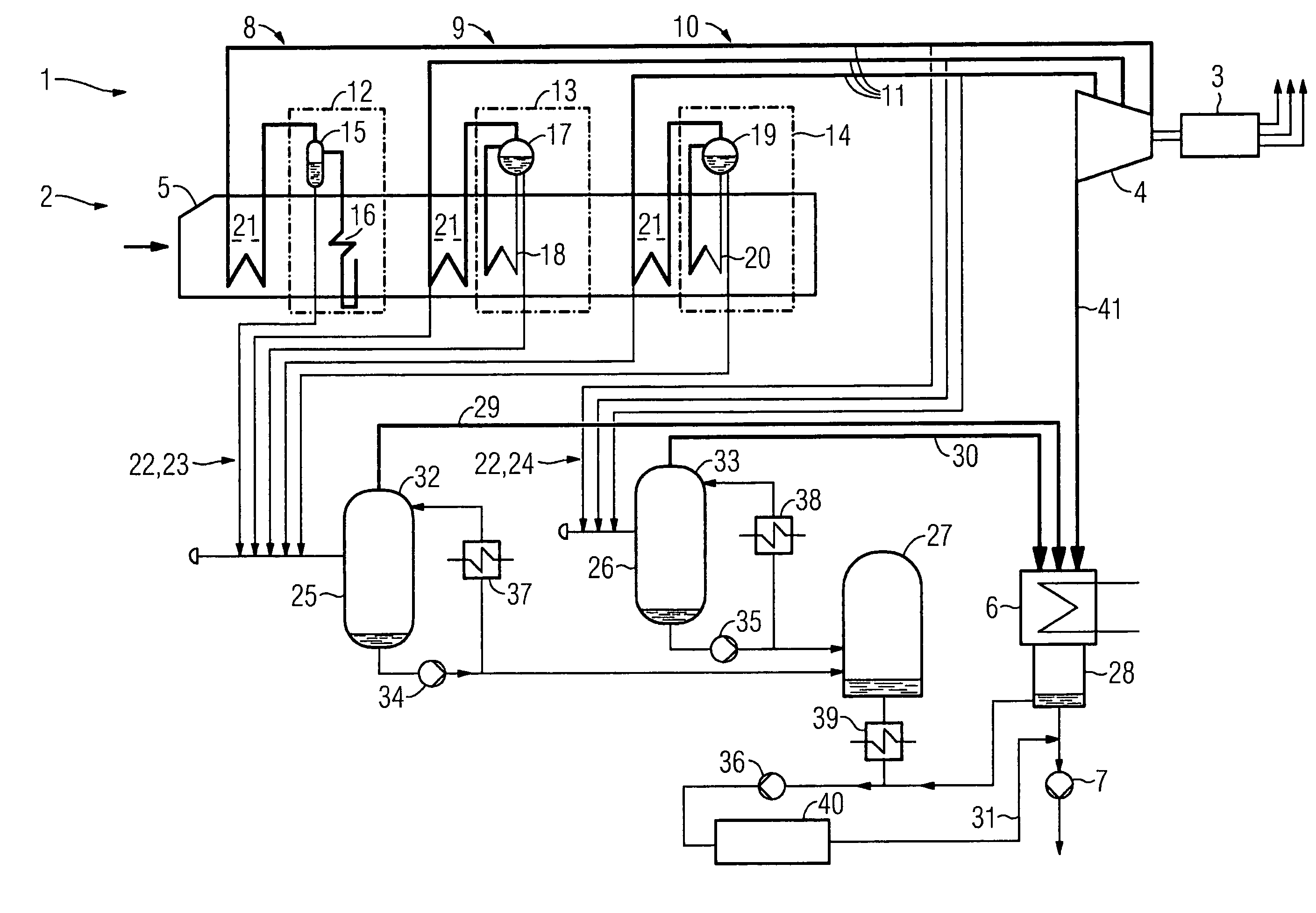
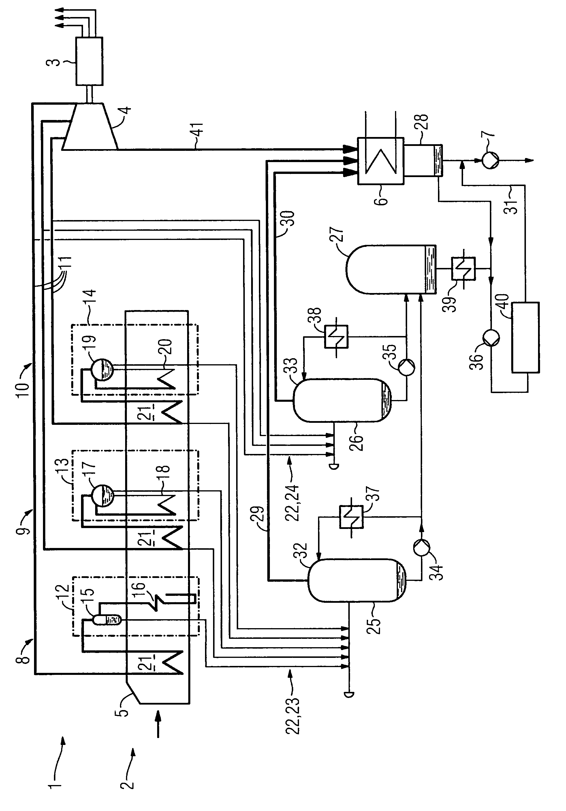
[0019]FIG. 1 shows a first exemplary embodiment of a steam power plant 2 according to the invention. The steam power plant 2 is an integral part of a power plant 1, which can also be implemented for instance as a combined gas and steam turbine power plant. The steam power plant 2 has a steam turbine 4 with, in this exemplary embodiment, three different pressure areas. In the exemplary embodiment, the steam power plant 2 also has a water circuit essentially comprising the steam turbine 4, a condenser 6, a condensate pump 7 and three pressure stages 8, 9, 10 each assigned to the respective pressure areas of the steam turbine 4. The water circuit additionally comprises a feed water pump (not shown). The pressure stages 8, 9, 10 are connected to the pressure areas of the steam turbine 4 by steam pipes 11. In the exemplary embodiment, the pressure stages 8, 9, 10 are made up of the first pressure stage 8 embodied as a high-pressure stage, the second pressure stage 9 embodied as a medium-...


PUM


Abstract

The invention relates to a method for operating a steam power station and a power plant as well as a corresponding steam power station. According to the invention, essentially all of the water that is drained from at least one pressure stage of the steam power station is collected, stored, and recirculated into the water circuit of steam power station.

Description

CROSS REFERENCE TO RELATED APPLICATIONS[0001]This application is the US National Stage of International Application No. PCT / EP2005 / 056008, filed Nov. 16, 2005 and claims the benefit thereof. The International Application claims the benefits of European application No. 04028295.6 filed Nov. 30, 2004, both of the applications are incorporated by reference herein in their entirety.FIELD OF INVENTION[0002]The present invention relates to a method for operating a steam power plant and in particular a method for operating a power plant for generating at least electrical energy using a steam power plant, said steam power plant having a water circuit with at least one pressure stage and water being drainable if necessary from the water circuit or pressure stages. The power plant has at least one electrical generator which can be driven by the steam power plant. The invention additionally relates to a steam power plant for generating at least electrical energy on which the method according t...

Claims


Application Information

Patent Timeline
Patent Type & Authority Patents(United States)
IPC IPC(8): F01K7/34F01K7/22
CPCF01K21/06F01K23/106F01K13/00F01K23/10
Inventor SCHOTTLER, MICHAELWALLMANN, ANJAWULFF, RAINER
Owner SIEMENS AG
Why Eureka
Try Eureka