Object storage tray

a technology for objects and storage racks, applied in drawers, cabinets, plates, etc., can solve the problems of frequent instability and tipping, difficult access, scratching and denting, etc., and achieves low manufacturing cost, easy and efficient manufacturing and marketing, and low price of sale.

Inactive Publication Date: 2011-02-15
BERGER STUART
View PDF17 Cites 21 Cited by
  • Summary
  • Abstract
  • Description
  • Claims
  • Application Information

AI Technical Summary

Benefits of technology

[0029]It is therefore an object of the present invention to provide a new and improved object storage tray that has all of the advantages of the prior art expandable racks for dishes and platters and none of the disadvantages.
[0030]It is another object of the present invention to provide a new and improved object storage tray that may be easily and efficiently manufactured and marketed.
[0031]An even further object of the present invention is to provide a new and improved object storage tray that has a low cost of manufacture with regard to both materials and labor, and which accordingly is then susceptible to low prices of sale to the consuming public, thereby making such object storage tray economically available to the buying public.
[0032

Problems solved by technology

Such stacks are frequently unstable and tip over, and often the desired cooking utensil is underneath other objects, making it difficult to access.
The pots, pans, and lids are also in physical contact with one another, leading to scratching and denting.
'108 patent does not have pivoting and sliding dividers, and has further drawbacks of lacking a lid handle notch.
However, the Remmers 2004/0095048 patent application publication does not have dividers that pivot, and does not have dividers with an unattached edge.
However, the Harbison 2006/0267467 patent application publication does not have dividers that slide and pivot, and also does not have a lid handle notch.
However, the Morgan '870 patent does not have dividers that slide and pivot, and further lacks a lid handle notch.
However, the Khan '676 patent does not have a divider that slides and pivots, and has the additional deficiency of lacking a lid handle notch.
However, the Remmers '629 patent does not have dividers that slide and pivot, and also does not have a lid handle notch.
However, the Morgan '672 patent does not have dividers that slide and pivot, and further lacks a lid handle not

Method used


Image

  • Object storage tray
  • Object storage tray
  • Object storage tray

Examples


Embodiment Construction

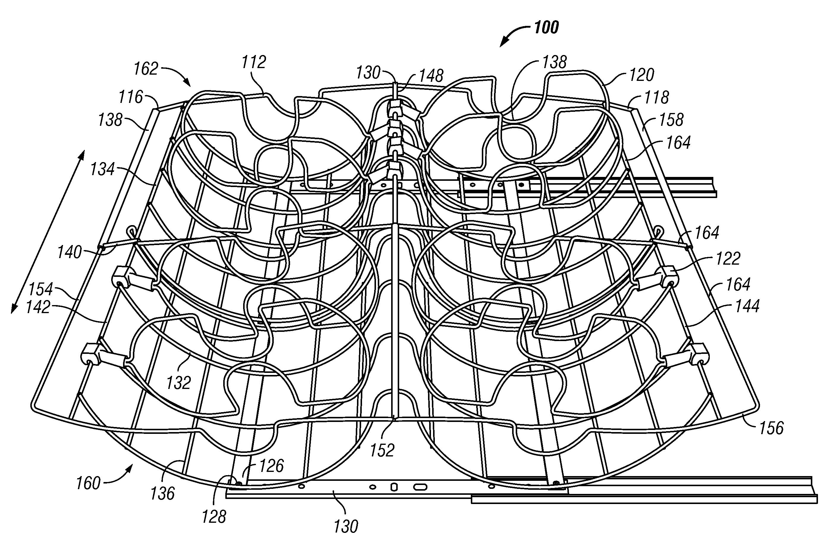
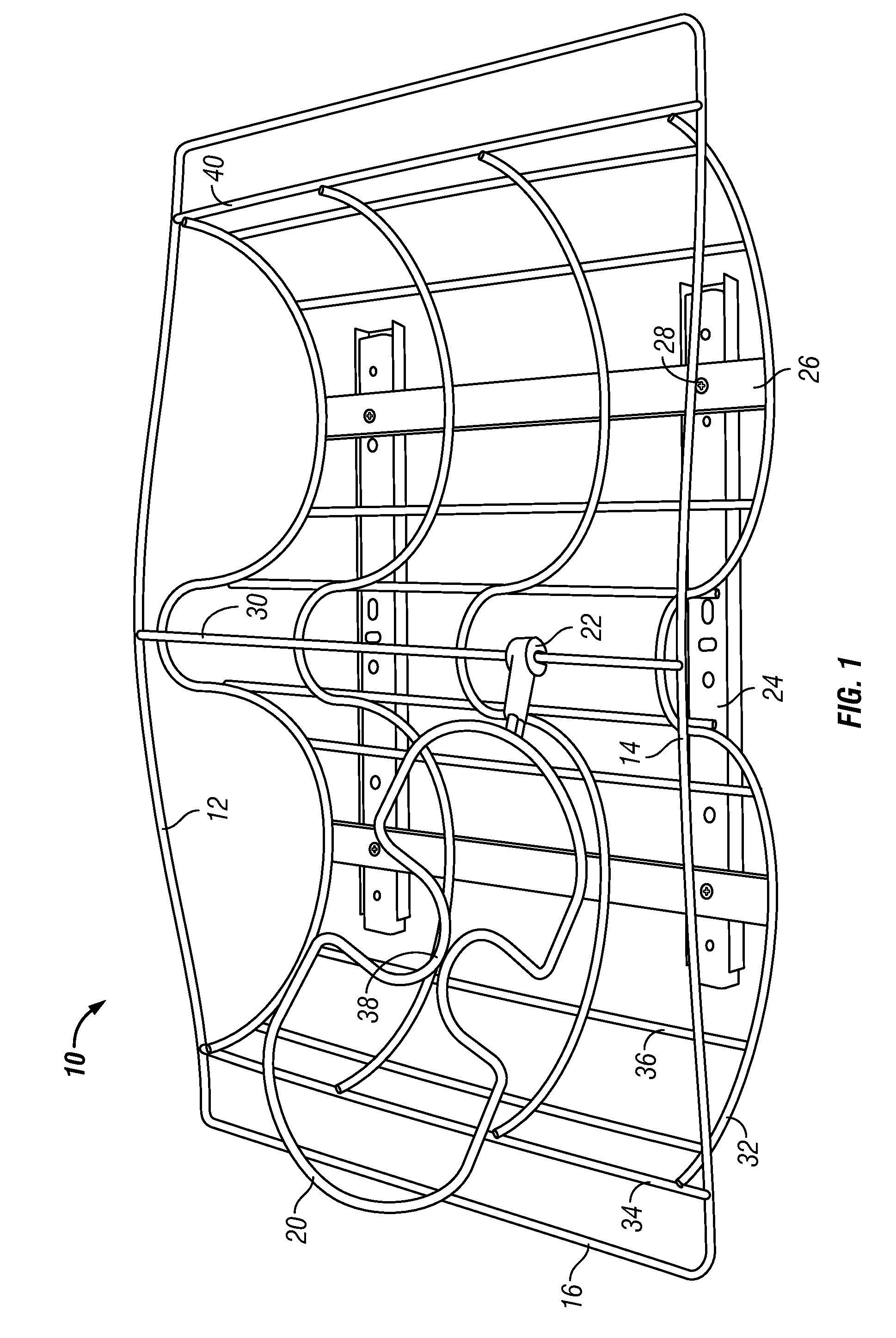
[0049]Referring now to the drawings, and particularly to FIGS. 1-5, a current embodiment of the object storage tray of the present invention is shown and generally designated by the reference numeral 10.

[0050]In FIG. 1, a new and improved object storage tray 10 of the present invention for providing a tray for storing pots, pans, and their lids is illustrated and will be described. More particularly, the object storage tray 10 has a first top member 12 with its opposing ends connected to the opposing ends of second top member 14 by the opposing ends of first end member 16, first cross member 34, second end member 18, and second cross member 40. The middles of the first top member 12 and second top member 14 are joined by the opposing ends of first center member 30. Four longitudinal members 32 have their opposing ends joined to first cross member 34 and second cross member 40, respectively. The middle of longitudinal members 32 is attached to first center member 30. The longitudinal...


PUM


Abstract

Object storage trays provide a tray for storing pots, pans, and their lids. First and second top members and first and second end members form a generally rectangular frame attached to a first center member, a first cross member, and a second cross member. Generally sinusoidal longitudinal members are attached to the first cross member, first center member, and second cross member. Glider brackets are attached beneath the longitudinal members to connect gliders to the object storage tray. Dividers mounted on sliding pivots are attached to the first center member and have lid handle notches in their middles. A telescoping embodiment of the invention is also disclosed that permits adjustments to the width of the object storage tray.

Description

BACKGROUND OF THE INVENTION[0001]1. Field of the Invention[0002]The present invention relates to an object storage tray for use in connection with object storage. The object storage tray has particular utility in connection with providing a tray for storing pots, pans, and their lids.[0003]2. Description of the Prior Art[0004]Object storage trays are desirable for providing a tray for storing pots, pans, and their lids. Many kitchens have cabinets filled with a chaotic assortment of pots, pans, and their lids. Typically, in order to maximize storage space, pots, pans, and their lids are stacked, resulting in nested pots. Such stacks are frequently unstable and tip over, and often the desired cooking utensil is underneath other objects, making it difficult to access. The pots, pans, and lids are also in physical contact with one another, leading to scratching and denting. The current invention overcomes these difficulties by storing pots, pans, and their lids on their sides with divi...

Claims


Application Information

Patent Timeline
IPC IPC(8): A47G29/00A47G19/08
CPCA47B45/00A47B81/04A47B88/20A47J47/16A47B88/90A47B88/988
Inventor BERGER, STUART
Owner BERGER STUART
Why Eureka
Try Eureka