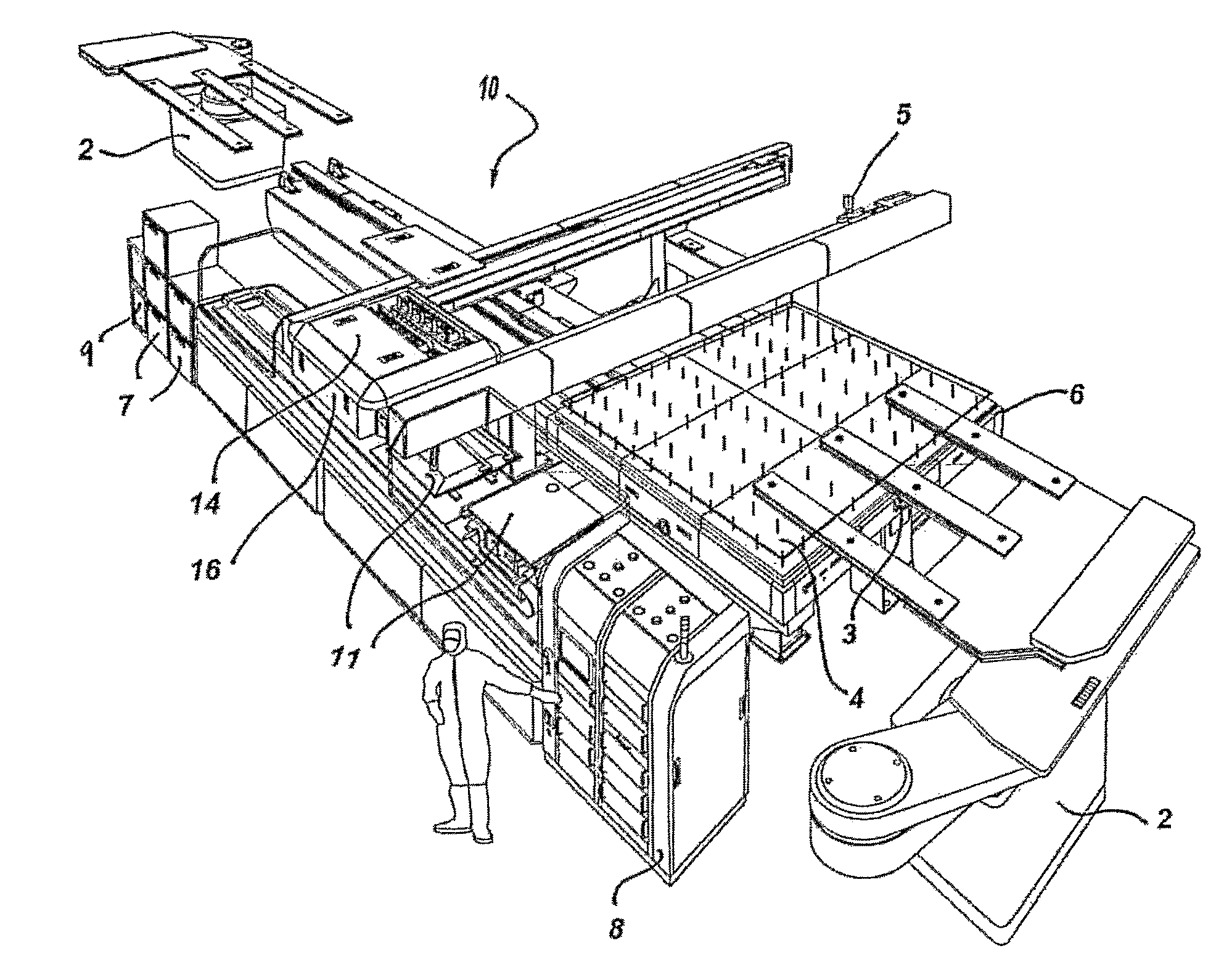
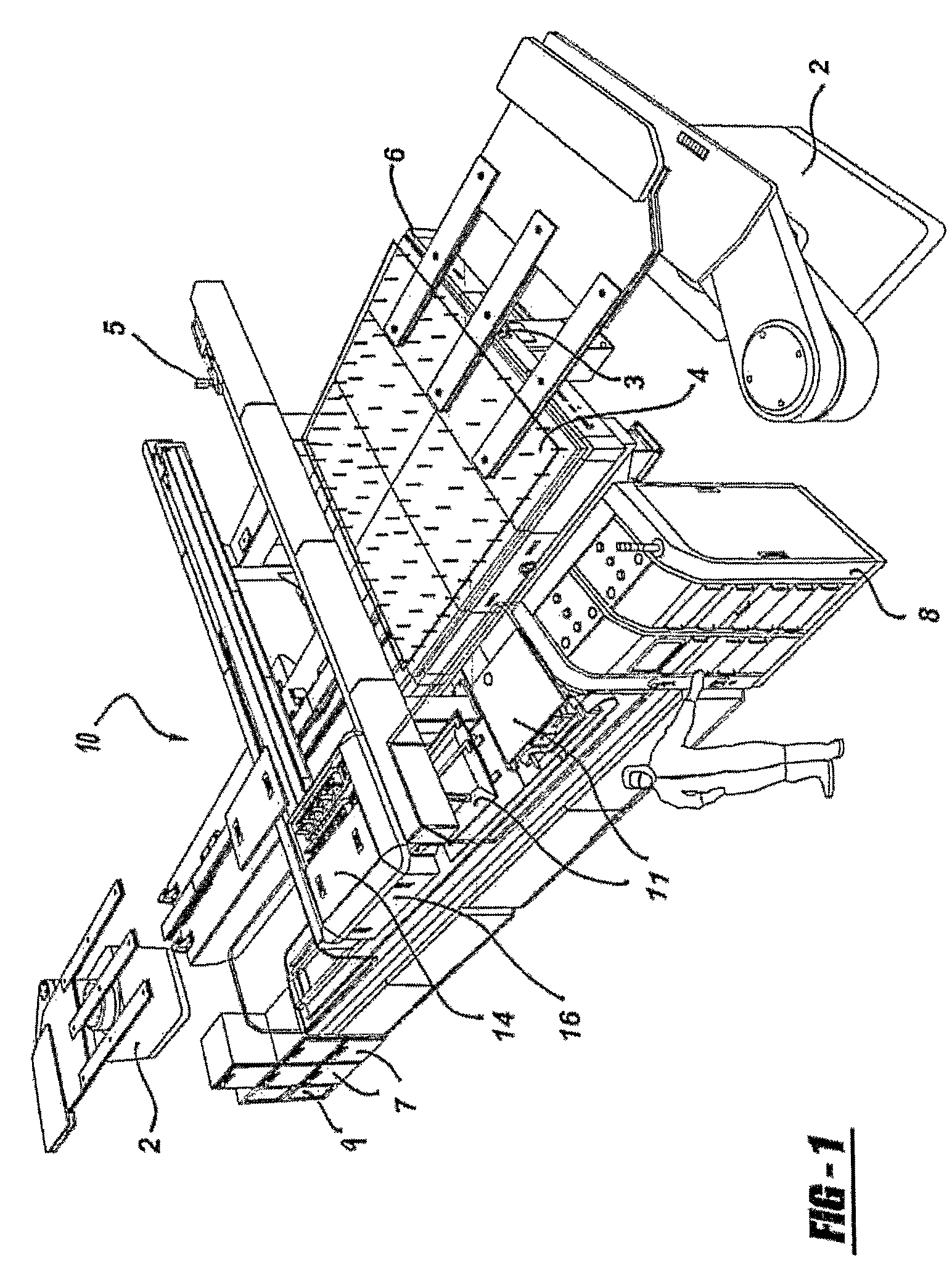
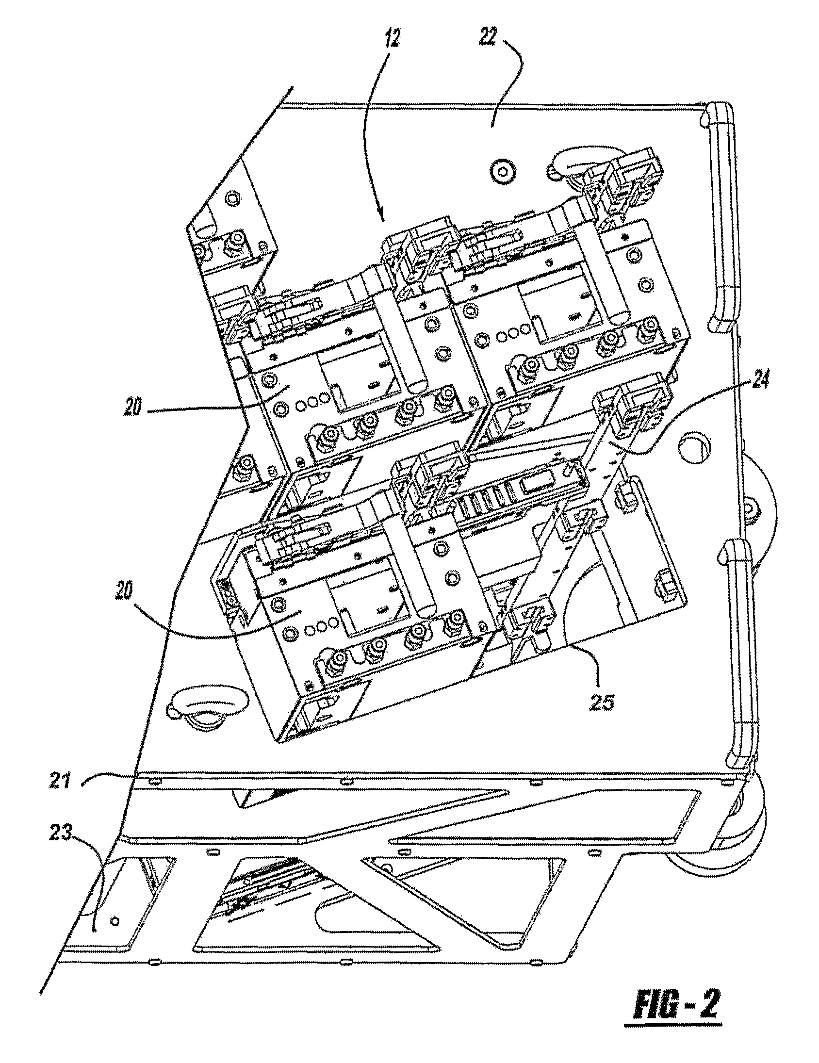
Integral printhead assembly

a printhead and assembly technology, applied in the direction of printing, coatings, other printing apparatus, etc., can solve the problems that the transfer rate required for a central computer may become impractical, and achieve the effect of increasing throughput and larger substrate sizes

Inactive Publication Date: 2011-02-15
ULVAC INC
View PDF22 Cites 23 Cited by
  • Summary
  • Abstract
  • Description
  • Claims
  • Application Information

AI Technical Summary

Benefits of technology

[0005]By processing the data in each printhead assembly, the integral printhead assembly can account for both linear and non-linear distortion of the substrate, and to limit production delays the integral printhead assembly can be tested and calibrated off-line using a fixture that can interface to the PC inside the integral printhead assembly and also supply the fluid and pressure controls. The fixture would have an optical system capable of measuring the ejected droplets from the printhead and measuring the velocity, directionality, and volume. Based on a compensation algorithm, new drive waveforms would be downloaded to the integral printhead assembly until the required performance for these parameters is achieved. Once achieved, the drive waveforms are stored in a non-volatile memory of a databoard assembly located within the integral printhead assembly along with its serial number, date of testing, pressure and vacuum levels at adjustment, and any other process information that is desired. The integral printhead assembly would be kept in a ready state for quick replacement of a failed printhead in the production array of integral printheads being used by the PMD manufacturing tool. This fixture may include one drop check unit that can service multiple integral printhead assemblies that are kept in standby ready for transfer.

Problems solved by technology

While a central computer could perform this function and dispatch the data to the printheads, as the need for 20 to 40 printheads becomes common for larger substrate sizes, such as the manufacture of large flat panel displays by way of non-limiting example, the transfer rates required for a central computer may become impractical.

Method used


Image

  • Integral printhead assembly
  • Integral printhead assembly
  • Integral printhead assembly

Examples


Embodiment Construction

[0013]The following description is merely exemplary in nature and is in no way intended to limit the teachings, its application, or uses.

[0014]The terms “fluid manufacturing material,”“fluid material,” and “printing fluid,” as defined herein, are broadly construed to include any material that can assume a low viscosity form and that is suitable for being deposited, for example, from a PMD head onto a substrate for forming a microstructure. Fluid manufacturing materials may include, but are not limited to, light-emitting polymers (LEPs), which can be used to form polymer light-emitting diode display devices (PLEDs, and PolyLEDs). Fluid manufacturing materials may also include inks, plastics, metals, waxes, solders, solder pastes, biomedical products, acids, photoresists, solvents, adhesives, and epoxies. The term “fluid manufacturing material” is interchangeably referred to herein as “fluid material” or “printing fluid.”

[0015]The term “deposition,” as defined herein, generally refers...


PUM


Abstract

The present invention relates to an integral printhead assembly for use in association with an industrial printing apparatus. The integral printhead assembly is a self-contained unit which can be quickly removed and replaced with another assembly with minimum downtime to the printing apparatus.

Description

CROSS-REFERENCE TO RELATED APPLICATIONS[0001]This application is a National Stage of International Application No. PCT / US2006 / 015614, filed Apr. 25, 2006, and claims the benefit of U.S. Provisional Application Nos. 60 / 674,584, 60 / 674,585, 60 / 674,588, 60 / 674,589, 60 / 674,590, 60 / 674,591, and 60 / 674,592, all filed on Apr. 25, 2005. The disclosures of the above applications are incorporated herein by reference.FIELD[0002]The present teachings relate to an integral printhead assembly for use in an individual printing apparatusBACKGROUND[0003]In piezoelectric microdeposition (PMD) apparatuses, machine down time resulting from switching out ineffective printheads should be minimized. Generally, when a printhead fails, the entire PMD printing operation has to be stopped so that the printhead can be changed. Once changed, the printhead has to be calibrated and tested on-line to ensure it is functional prior to bringing the PMD back up for production. However, calibration and testing typicall...

Claims


Application Information

Patent Timeline
Patent Type & Authority Patents(United States)
IPC IPC(8): B41J2/015
CPCB41J2/14201B41J2/155B41J29/393B41J29/38B05C5/00
Inventor MIDDLETON, JAMES N.ALBERTALLI, DAVIDPARKS, PAUL A.SRAMEK, DANIEL
Owner ULVAC INC
Why Eureka
Try Eureka