Insulative housing and electrical connector with an insulative housing

a technology of insulating housing and electrical connector, which is applied in the direction of coupling device connection, coupling protective earth/shielding arrangement, electric discharge lamps, etc., can solve the problem that the usb 2.0 transmission protocol does not meet the current transmission speed requirement of these electronic devices, and the usb 3.0 transmission protocol does not meet the current transmission speed requirement. problem, to prevent the terminal from electromagnetic interferen

Active Publication Date: 2011-02-15
ADVANCED CONNECTEK INC
View PDF9 Cites 37 Cited by
  • Summary
  • Abstract
  • Description
  • Claims
  • Application Information

AI Technical Summary

Benefits of technology

[0008]The main objective of the invention is to provide an electrical connector that complies with USB 2.0 and 3.0 transmission protocols and has a terminal shield shielding and preventing terminals from electromagnetic interference.
[0009]An electrical connector in accordance with the present invention has an insulative housing, a plurality of first terminals and a plurality of second terminals. The first and second terminals are mounted in the insulative housing and each terminal has a soldering segment. The insulative housing has rows of ventilation holes exposing the second terminals in the air so that transmitting high frequency signals on the second terminals is stable.

Problems solved by technology

However, the USB 2.0 transmission protocol only allows a maximum transmission speed of 480 Mbps.
Because electronic devices are constantly developed to increase transmission speed, the USB 2.0 transmission protocol does not meet the current transmission speed requirement of these electronic devices.
Transmitting high frequency signals usually encounters electromagnetic interference from nearby electronic components so that the impedance of the USB 3.0 connector unstably alternates and reduces signal transmission.
Furthermore, a manufacturer of the USB 3.0 connector frequently encounters connector mating problems.
One manufacturer's USB 3.0 receptacle connector mates a self-made plug connector to pass through an impedance test however does not mates plug connector produced by other manufacturers well and fails the impedance test so that signal transmission between USB 3.0 connectors by different manufacturers is unenforceable.

Method used


Image

  • Insulative housing and electrical connector with an insulative housing
  • Insulative housing and electrical connector with an insulative housing
  • Insulative housing and electrical connector with an insulative housing

Examples


Embodiment Construction

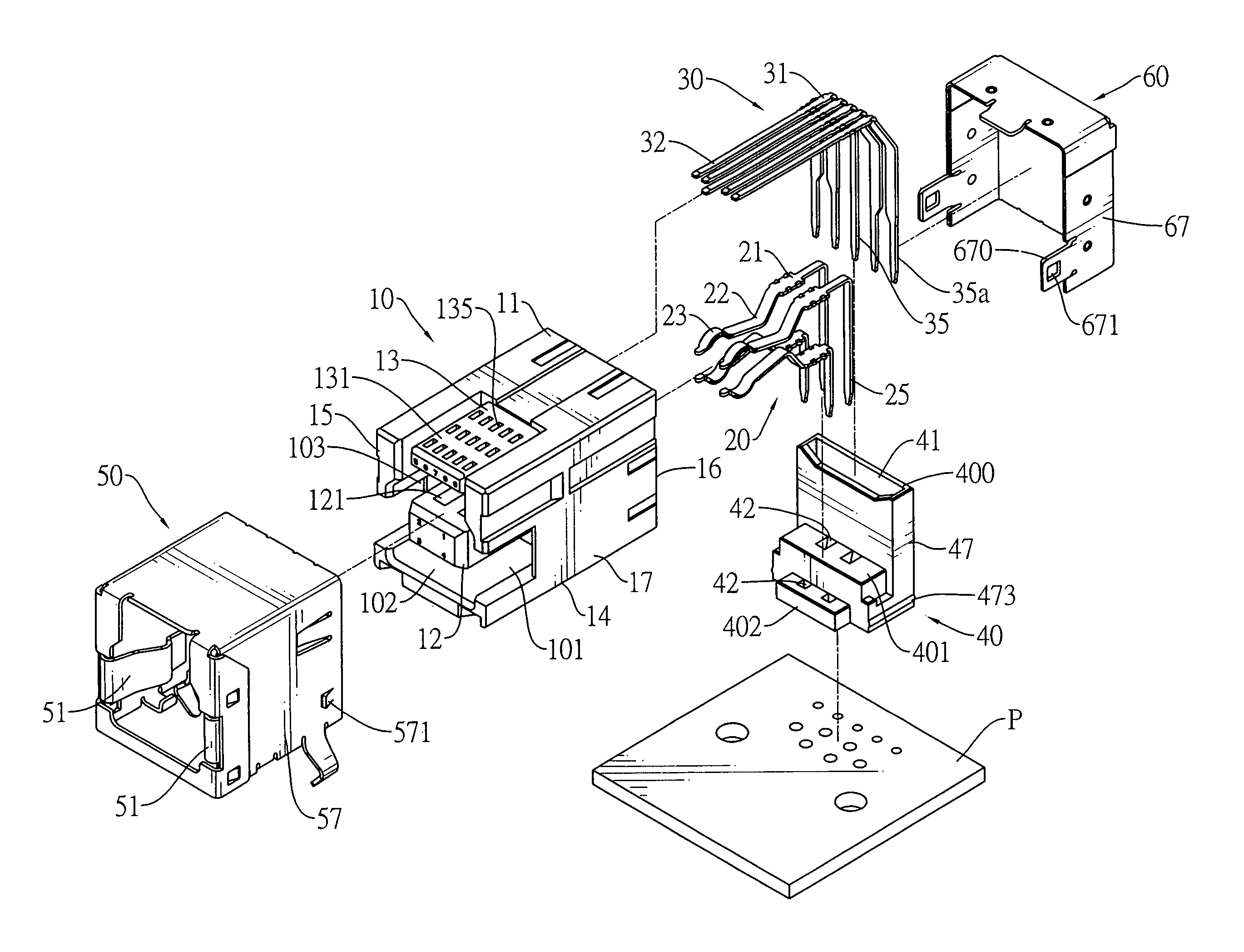
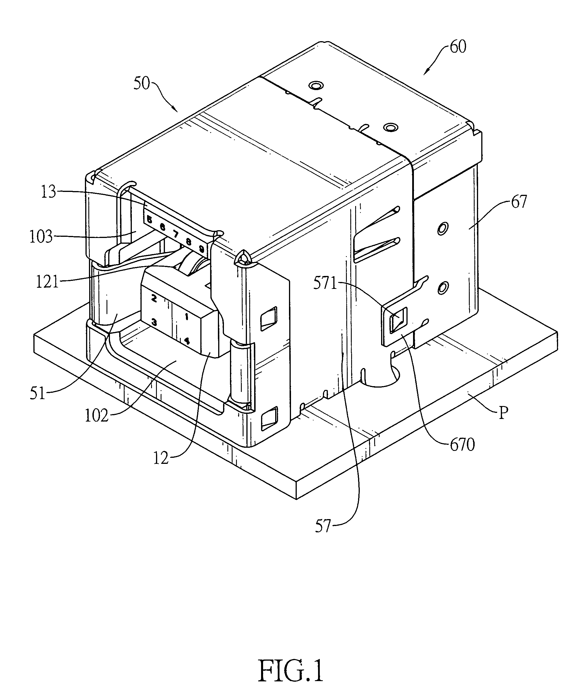
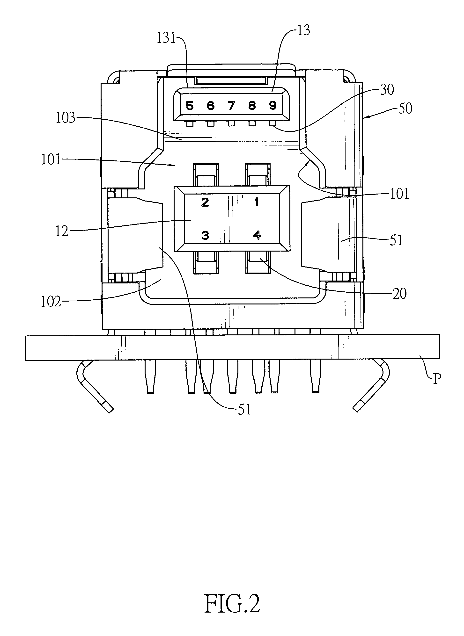
[0022]With reference to FIGS. 1 to 4, an electrical connector in accordance with the present invention may be a receptacle connector complying with USB 2.0 and 3.0 transmission protocols and mounted on a PCB (P).

[0023]The electrical connector comprises an insulative housing (10), a plurality of first terminals (20), a plurality of second terminals (30), a terminal shield (40) and a metal shell assembly.

[0024]With further reference to FIGS. 5, 6, 9 and 10, the insulative housing (10) has a top (11), a bottom (14), a front (15), a rear (16), two opposite sides (17), a cavity (101), a first tongue (12), a second tongue (13) and an opening (161) and may further have a plurality of first terminal holes (100a), a plurality of second terminal holes (100b), an alignment recess (162) and two mounting recesses (163).

[0025]The cavity (101) is defined in the front (15) and has an inner surface.

[0026]The first tongue (12) is formed on and protrudes forwards from the inner surface of the cavity (...


PUM


Abstract

An electrical connector has an insulative housing, a plurality of first terminals, a plurality of second terminals and a terminal shield. The first and second terminals are mounted in the insulative housing and each terminal has a soldering segment. The terminal shield substantially shields the soldering segments of the second terminals and prevents electromagnetic interference so that transmitting high frequency signals on the second terminals is stable.

Description

BACKGROUND OF THE INVENTION[0001]1. Field of the Invention[0002]The present invention relates to a connector, and more particularly to an electrical connector that complies with USB (Universal Serial Bus) 2.0 and 3.0 transmission protocols and has a terminal shield shielding and preventing terminals from electromagnetic interference.[0003]2. Description of Related Art[0004]Conventional USB 2.0 connectors are popular in various electronic devices. However, the USB 2.0 transmission protocol only allows a maximum transmission speed of 480 Mbps. Because electronic devices are constantly developed to increase transmission speed, the USB 2.0 transmission protocol does not meet the current transmission speed requirement of these electronic devices. Therefore, the USB IF (USB Implementers Forum) is setting up a USB 3.0 transmission protocol that may achieve a theoretical maximum transmission speed of 4.8 Gbps, almost 10 times of that of the USB 2.0 transmission protocol.[0005]However, to im...

Claims


Application Information

Patent Timeline
Patent Type & Authority Patents(United States)
IPC IPC(8): H01R33/00
CPCH01R13/506H01R12/712H01R27/00H01R13/65802H01R13/6582
Inventor CHEN, CHING-TIENHOU, PIN-YUANKO, WEN-CHIH
Owner ADVANCED CONNECTEK INC
Why Eureka
Try Eureka