
LED lamp

a technology of led lamps and leds, which is applied in the field of led lamps, can solve the problems of increasing the price and power consumption of modules, unsuitable for environments requiring even and broad illumination, and the inability of leds mounted on the flattened surface of printed circuit boards to have a large illumination area

Inactive Publication Date: 2011-02-15
FU ZHUN PRECISION IND SHENZHEN +1
View PDF5 Cites 19 Cited by
  • Summary
  • Abstract
  • Description
  • Claims
  • Application Information

AI Technical Summary

Benefits of technology

[0005]Known implementations of LED modules in an LED lamp make use of a plurality of individual LEDs to generate light that is ample and of satisfactory spatial distribution. The large number of LEDs, however, increases price and power consumption of the module. Considerable heat is also generated, which, if not adequately addressed at additional expense, impacts LED lamp reliability.

Problems solved by technology

The large number of LEDs, however, increases price and power consumption of the module.
Considerable heat is also generated, which, if not adequately addressed at additional expense, impacts LED lamp reliability.
Further, since the LEDs are generally arranged on a printed circuit board having a flattened surface, illumination is distributed at a wide variety of spatial angles with sharp differences in intensity and brightness, making it unsuitable for environments requiring even and broad illumination.
Finally, the LEDs mounted on the flattened surface of the printed circuit board cannot have a large area of illumination.

Method used


Image

  • LED lamp
  • LED lamp
  • LED lamp

Examples


Embodiment Construction

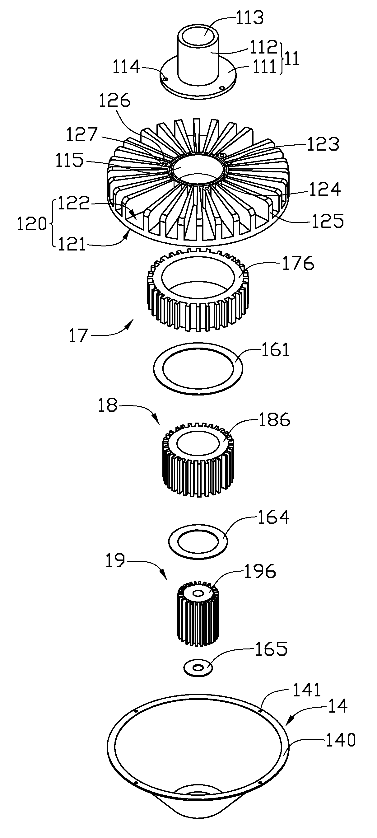
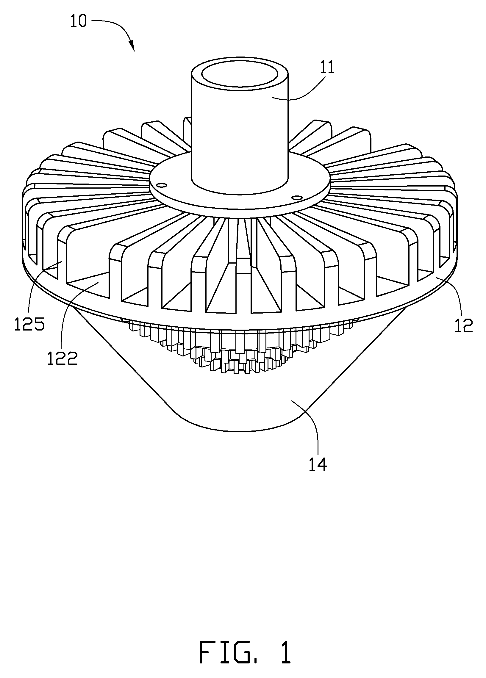
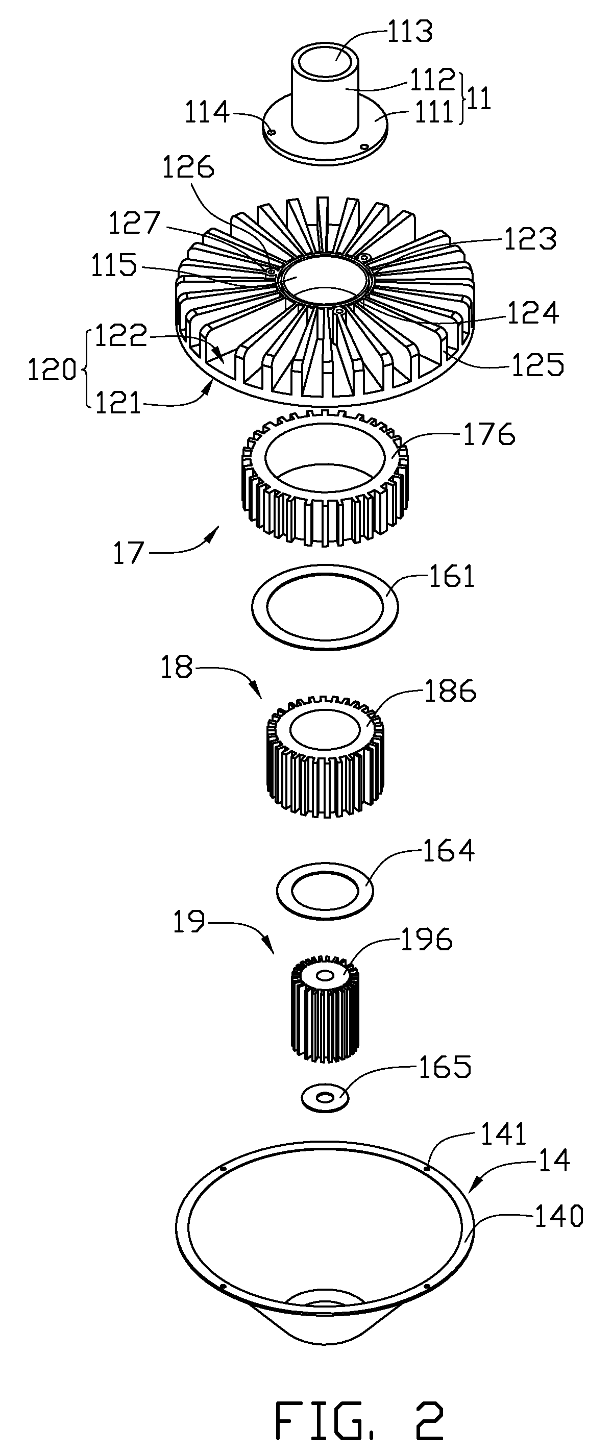
[0013]Referring to FIGS. 1-4, an LED lamp 10 in accordance with an exemplary embodiment is illustrated. The LED lamp 10, which is configured for providing illumination indoors and outdoors, includes a base 12, a mounting member 11 coupled to a top of the base 12, a first heat sink 17, a second heat sink 18, a third heat sink 19, a first LED module 161, a second LED module 164, a third LED module 165 and a cover 14 located under the base 12. The first heat sink 17, the second heat sink 18 and the third heat sink 19 are located under and contact with a bottom surface 121 of the base 12. The first LED module 161, the second LED module 164 and the third LED module 165 correspond to and are mounted on the first heat sink 17, the second heat sink 18 and the third heat sink 19, respectively. The cover 14 engages with the bottom surface 121 of the base 12 to enclose the heat sinks 17, 18, 19 and the LED modules 161, 164, 165 therein.

[0014]The base 12 is made of a metal having a high heat co...


PUM

PropertyMeasurementUnit
heat absorbingaaaaaaaaaa
heightaaaaaaaaaa
bore diameteraaaaaaaaaa

Abstract

An LED lamp includes a base, at least first and second heat sinks, and at least first and second LED modules. The first heat sink includes a first heat absorbing surface and a first mounting surface which is mounted to the base, and defines axially a first through hole. The second heat sink includes a second heat absorbing surface and a second mounting surface which is mounted to the base. The second heat sink is received in the first through hole of the first heat sink. The second heat sink has a height greater than a height of the first heat sink whereby the second heat absorbing surface extends out of the first heat sink. The first and second LED modules are mounted on the first and second heat absorbing surfaces, respectively.

Description

BACKGROUND[0001]1. Technical Field[0002]The disclosure relates to an LED (light-emitting diode) lamp, and more particularly to an improved LED lamp capable of illuminating a large area.[0003]2. Description of Related Art[0004]An LED lamp utilizes LEDs as a source of illumination, in which current flowing in one direction through a junction region comprising two different semiconductors results in electrons and holes coupling at the junction region and generating a light beam. The LED is resistant to shock and has an almost endless lifetime under specific conditions, making it a popular, cost-effective and high quality replacement for incandescent and fluorescent lamps.[0005]Known implementations of LED modules in an LED lamp make use of a plurality of individual LEDs to generate light that is ample and of satisfactory spatial distribution. The large number of LEDs, however, increases price and power consumption of the module. Considerable heat is also generated, which, if not adequa...

Claims


Application Information

Patent Timeline
Patent Type & Authority Patents(United States)
IPC IPC(8): H05B33/00F21V29/00
CPCF21K9/00F21V29/83F21V29/773F21V29/70F21V21/116F21Y2101/02F21Y2103/022F21Y2111/001F21Y2111/008Y10S362/80H01L2924/0002H01L2924/00F21Y2115/10F21Y2103/33F21Y2107/00F21Y2107/60F21V3/062F21V3/061
Inventor YANG, RI-LANGYU, GUANG
Owner FU ZHUN PRECISION IND SHENZHEN
Learn More