Magnetic levitation sliding structure

a sliding structure and magnetic levitation technology, applied in the direction of magnets, magnetic bodies, electric apparatus casings/cabinets/drawers, etc., can solve the inconvenience of operating operations of users, and achieve the effects of stable sliding structure, long sliding stroke, and low friction

Inactive Publication Date: 2011-02-15
HANWHA TECHWIN CO LTD
View PDF18 Cites 51 Cited by
  • Summary
  • Abstract
  • Description
  • Claims
  • Application Information

AI Technical Summary

Problems solved by technology

Accordingly, a user must undergo the inconvenience of operating operation-keys that are spaced apart from one another to perform different functions.

Method used


Image

  • Magnetic levitation sliding structure
  • Magnetic levitation sliding structure
  • Magnetic levitation sliding structure

Examples


Embodiment Construction

[0038]Hereinafter, exemplary embodiments of the invention will be described with reference to the attached drawings.

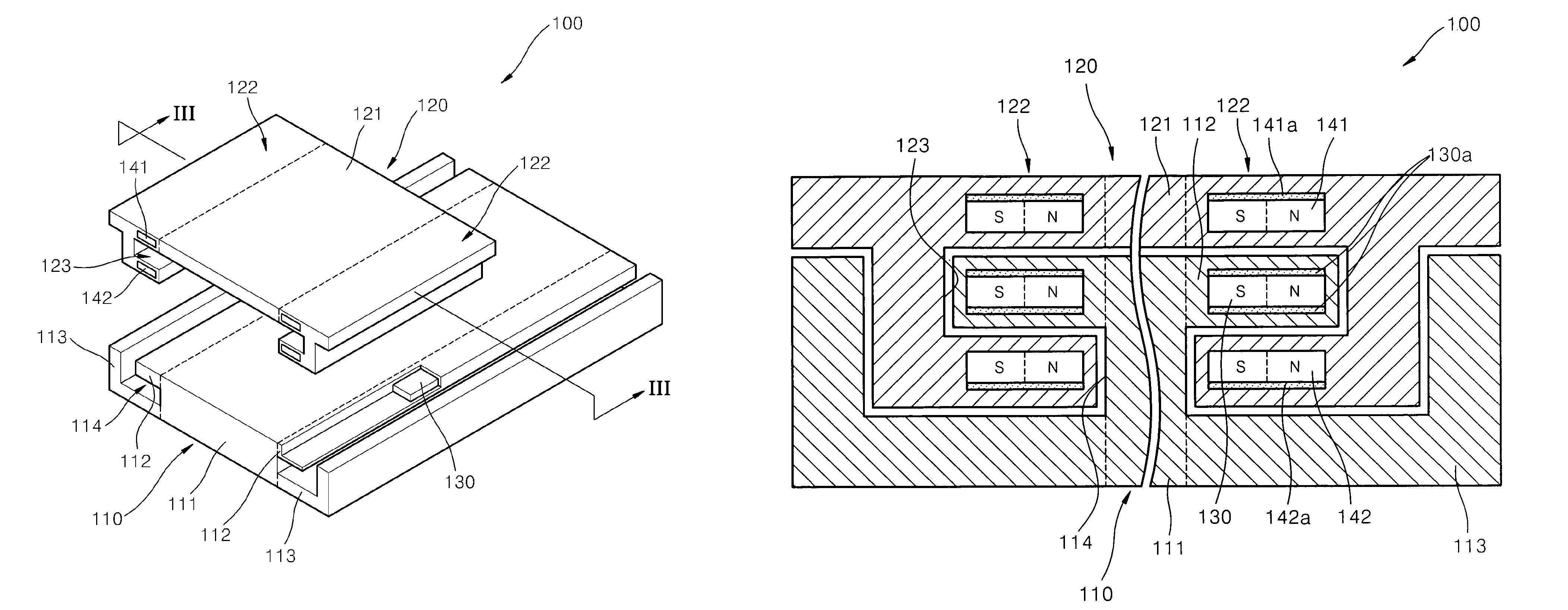
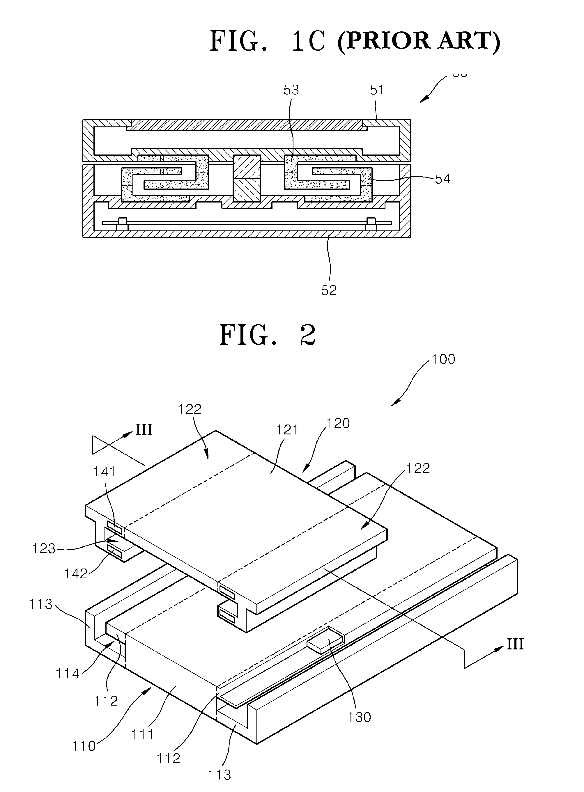
[0039]FIG. 2 is a perspective view illustrating a sliding structure 100, according to an embodiment of the present invention. FIG. 3 is a view of the sliding structure 100 taken along a line III-III of FIG. 2. FIG. 4 is a schematic perspective view illustrating the arrangement of a first magnet portion 130, and second magnet portions 141 and 142 in the sliding structure 100, according to an embodiment of the present invention.

[0040]Referring to FIGS. 2 and 3, the sliding structure 100 includes a first sliding member 110, a second sliding member 120, the first magnet portion 130 and the second magnet portions 141 and 142. The first sliding member 110 is formed of a non-magnetic material such as an aluminum alloy and includes a support portion 111, a guide portion 112, and an auxiliary receiving portion 113. In this example, the support portion 111 has a flat or substant...


PUM

PropertyMeasurementUnit
magnetic polesaaaaaaaaaa
repulsive forceaaaaaaaaaa
cross-sectional shapeaaaaaaaaaa

Abstract

A low friction and stable sliding structure for an electronic device is provided. The sliding structure includes a first sliding member comprising at least one guide portion, a second sliding member including a receiving portion receiving the guide portion so as to slide along the first sliding member, a first magnet portion disposed in the guide portion, such that magnetic poles of the first magnet portion are arranged across a sliding direction, and a second magnet portion disposed in the receiving portion so that a repulsive force can act between the first magnet portion and the second magnet portion.

Description

CROSS-REFERENCE TO RELATED PATENT APPLICATION[0001]This application claims the benefit of Korean Patent Application No. 10-2007-0005818, filed on Jan. 18, 2007, in the Korean Intellectual Property Office, the disclosure of which is incorporated herein in its entirety by reference.BACKGROUND OF THE INVENTION[0002]1. Field of the Invention[0003]The present invention relates to a sliding structure for an electronic device, and more particularly, to a low friction and stable sliding structure for an electronic device.[0004]2. Description of the Related Art[0005]As sliding structures have the advantages of simple handling and attractive design, they are largely used in portable electronic devices such as cellular phones, cameras, portable multimedia players (PMP), electronic dictionaries, electronic schedulers, navigations, small-sized notebook computers or the like. FIG. 1A is a schematic perspective view illustrating a conventional cellular phone 10, and FIG. 1B is a schematic side vie...

Claims


Application Information

Patent Timeline
Patent Type & Authority Patents(United States)
IPC IPC(8): H01F7/02H04M1/00H01F7/20H01F7/00H01F7/08
CPCH04M1/0237H01F7/0236H04B1/38
Inventor CHO, SE-HOON
Owner HANWHA TECHWIN CO LTD
Why Eureka
Try Eureka