Image processing device, non-capture color signal calculating device, and image processing method

a color signal and image processing technology, applied in the field of image processing devices, can solve the problems of false colors, inability to achieve sufficient resolution, and resolutions corresponding to the number of pixels cannot be achieved for any of r, g, and b colors, and achieve the effect of suppressing image quality deterioration and high practical us

Inactive Publication Date: 2011-02-15
MITSUBISHI ELECTRIC CORP
View PDF12 Cites 10 Cited by
  • Summary
  • Abstract
  • Description
  • Claims
  • Application Information

AI Technical Summary

Benefits of technology

[0020]According to the present invention, in an image processing device for obtaining images from an image capture device in which photoelectric transducers, each having any one among first through N-th spectral sensitivity curves in a group of N spectral sensitivity curves, are arranged in a two-dimensional plane, the image processing device includes a first calculation means for calculating based on capture color signals for pixels surrounding a pixel of interest, outputted from those photoelectric transducers having an H-th spectral sensitivity curve, a non-capture color signal corresponding to an H-th interpolation color for the pixel of interest; a second calculation means for calculating a non-capture color signal corresponding to the H-th interpolation color for the pixel of interest by inputting capture color signals from the photoelectric transducers to two-dimensional low-pass filters to obtain two-dimensional low-pass filter outputs, and multiplying a signal for a J-th capture color, corresponding to the capture color of the pixel of interest by the ratio of the H-th two-dimensional low-pass filter output for the pixel of interest to the J-th two-dimensional low-pass filter output for the pixel of interest; and a third calculation means for calculating a non-capture color signal corresponding to the H-th interpolation color for the pixel of interest using the calculation result from the first calculation means and the calculation result from the second calculation means; so that an imaging device of high practical use that can well suppress image quality deterioration while achieving effects of the conventional technology 1 and the conventional technology 2 can be realized.

Problems solved by technology

However, there has been a problem in that the method in the conventional technology 1 cannot achieve sufficient resolutions, and false colors that are not present in the original subject are generated in edge portions in the image.
More specifically, because a single-color filter is disposed on each pixel to take images, spatial frequency characteristics and phases are various, so that the linear interpolation method in the conventional technology 1 cannot sufficiently restore high-frequency components, whereby resolutions corresponding to the number of pixels cannot be achieved for any of R, G, and B colors.
However, in edge areas of images in which variations in the signal level are precipitous, color signals to be interpolated cannot be sufficiently recreated, so that signal changes between colors are unbalanced, whereby the color signals are perceived as false colors that are originally not present.
More specifically, although the conventional technology 2 is an effective method with a high image quality and less false colors as a method of interpolating color signals in an imaging device with an image capture device, there has been a problem in that method-specific image quality deterioration is caused depending on effects of noise characteristic of sensors or on imaged pictures.Patent document 1: Japanese Patent Laid-Open No. 56446 / 1993Patent document 2: Japanese Patent Laid-Open No. 078211 / 2001Patent document 3: Japanese Patent Laid-Open No. 165894 / 2000Non-patent document 1: “National Technical Report” (Vol. 31; No. 1, February 1985), published by Matsushita Techno Research, Inc., released by Ohmsha, Ltd.

Method used


Image

  • Image processing device, non-capture color signal calculating device, and image processing method
  • Image processing device, non-capture color signal calculating device, and image processing method
  • Image processing device, non-capture color signal calculating device, and image processing method

Examples


embodiment 1

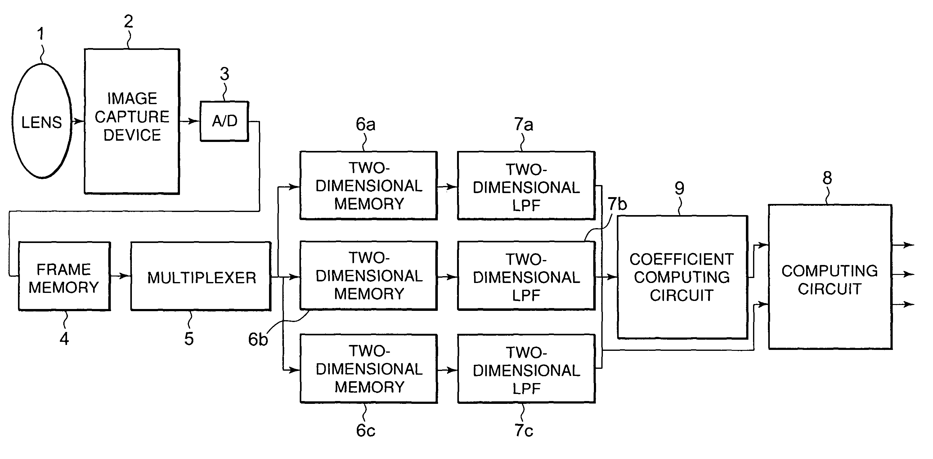
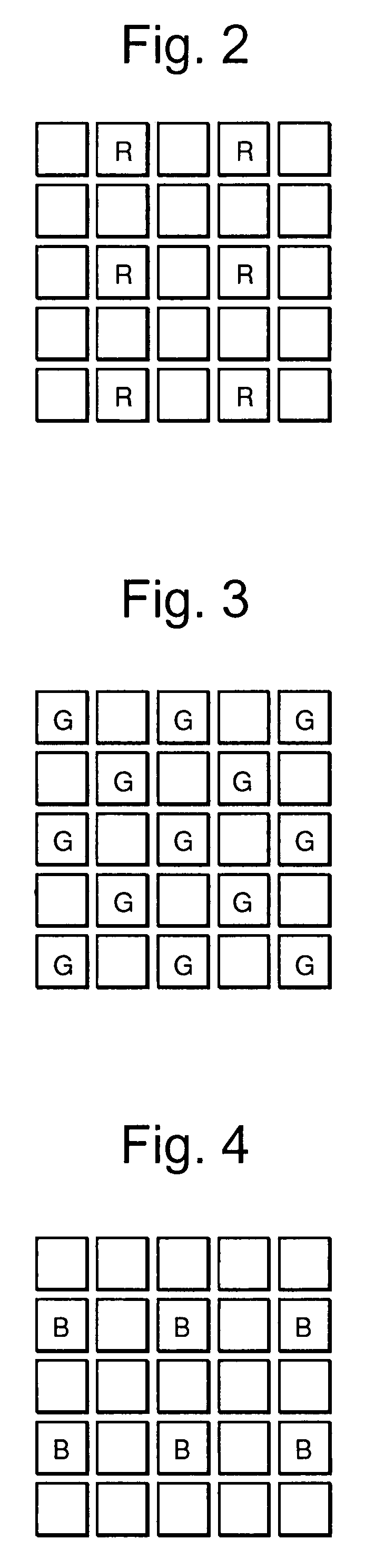
[0046]Hereinafter, Embodiment 1 of the present invention will be described in reference to drawings. FIG. 1 is an entire block diagram illustrating Embodiment 1 of the present invention. A case will be described in which, using an image capture device composed by arranging in a Bayer pattern photoelectric transducers on which color filters of three primary colors—R color, G color, and B color—are attached at digital still image composed of R, G, and B signals each expressed by 10 bits is realized by a digital still camera.

[0047]In FIG. 1, numeral 1 denotes a lens for collecting light incident from a subject; numeral 2 denotes an image capture device for photoelectric-converting the incident light through the lens; numeral 3 denotes A / D converter for converting analog image signals outputted from the image capture device into digital image signals; numeral 4 denotes a frame memory for temporarily storing digital image signals for one frame; numeral 5 denotes a multiplexer for separat...

embodiment 2

[0068]Hereinafter, Embodiment 2 will be described in reference to drawings. The block diagram illustrating the entire configuration of Embodiment 2 is FIG. 1 as the case of Embodiment 1. Regarding the internal configuration, only the difference from Embodiment 1 is that the coefficient computing circuit 9 includes Formula 19 for calculating the coefficient K.

[0069]Next, the operation will be described. In the present embodiment, the computation in the coefficient computing circuit 9 is performed according to Formula 19.

[0070][Expression⁢⁢19]K=(Dr-J(m,n)-JLPF)×JLPF-HLPFM(Formula⁢⁢19)

[0071]Provided that K≧1, then K=1.

[0072]Here, M is expressed as M=Dr2 in Embodiment 1, which has been used for normalizing the coefficient K. In the meanwhile, in Embodiment 2, after taking in advance into consideration of characteristics such as characteristics specific to the imaging system including the optical system and sensors, and noise characteristic due to sensitivity adjustments typified by anal...

embodiment 3

[0077]Hereinafter, Embodiment 3 will be described in reference to a diagram. FIG. 9 is a block diagram illustrating the entire configuration of Embodiment 3. Regarding the internal configuration, the difference from the conventional technologies is that Formula 10 is used in the computing circuit 8 for performing computation for color interpolation and a register 10 for providing the coefficient K in Formula 10 is added to the computing circuit.

[0078]In the operation in Embodiment 3, the coefficient K in Formula 10 is directly given in advance as a constant. In this regard, Embodiment 3 is different from Embodiment 1 in which the coefficient K is dynamically calculated from Formula 9, and is different from Embodiment 2 in which a user selects the M to dynamically calculate the coefficient K from Formula 19.

[0079]The coefficient K in this case can be changed for each image in accordance with imaging conditions as in Embodiment 1 and Embodiment 2. In Embodiment 3, however, unlike Embo...


PUM


Abstract

An image processing device includes a first calculation means for calculating a non-capture color signal corresponding to an H-th interpolation color for a pixel of interest, a second calculation means for calculating a non-capture color signal by multiplying a J-th capture color signal corresponding to the capture color for the pixel of interest by the ratio of the H-th two-dimensional low-pass filter output to the J-th two-dimensional low-pass filter output, and a third calculation means for calculating a non-capture color signal corresponding to the H-th interpolation color for the pixel of interest using the calculation result according to the first calculation means and the calculation result according to the second calculation means.

Description

TECHNICAL FIELD[0001]The invention relates to means for obtaining from each photoelectric transducer pseudo signal levels of R, G, and B colors, in which one kind of color filter for any of red (R color), green (G color), and blue (B color) is attached on each photoelectric transducer, a two-dimensional image capture device (hereinafter referred to as an image capture device) composed of photoelectric transducers two-dimensionally arranged as pixels for forming images is used, and color signals that cannot be obtained from each photoelectric transducer (interpolation colors) regarding image information obtained by imaging are calculated using color signals of the same color obtained from other photoelectric transducers arranged around that photoelectric transducer.BACKGROUND ART[0002]In an image input device using CCDs (charge coupled devices) as an image capture device, a method has been used for obtaining from each photoelectric transducer pseudo signal levels of R, G, and B color...

Claims


Application Information

Patent Timeline
Patent Type & Authority Patents(United States)
IPC IPC(8): H04N3/14H04N5/335H04N9/04H04N9/07
CPCG06T3/4015H04N9/045H04N2209/046H04N23/843H04N25/134
Inventor TAMURA, MASASHIMATOBA, NARIHIROSUGIURA, HIROAKIKUNO, TETSUYA
Owner MITSUBISHI ELECTRIC CORP
Why Eureka
Try Eureka