
Balanced and bi-directional bit line paths for memory arrays with programmable memory cells

a memory array and programmable memory technology, applied in the field of memory arrays, can solve the problems of lag in the initial heating rate of the memory cells, low power supply to the cells, and inability to meet the requirements of the memory array, so as to minimize the variation of the power delivery to the cells, minimize the electro-migration of the elements, and prolong the life of the memory cells.

Inactive Publication Date: 2011-02-15
IBM CORP
View PDF28 Cites 14 Cited by
  • Summary
  • Abstract
  • Description
  • Claims
  • Application Information

AI Technical Summary

Benefits of technology

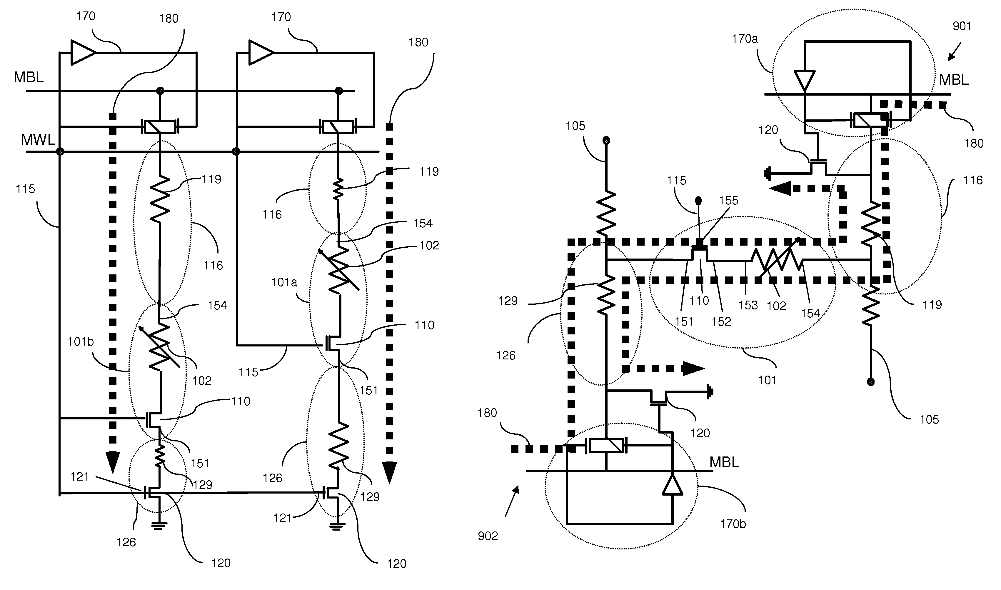
The patent describes an improved memory system that allows for bi-directional random access and minimizes power delivery variations to memory cells. The system includes a matrix of bit lines and word lines controlled by a matrix of bit line transistors. The transistors have consistent resistance in the write and read paths, regardless of position in the array. The system also includes isolation devices that establish current pathways through the memory cells. The current passing through each memory cell can be controlled by either a current source or voltage source. The system can be used for different types of random access memory that incorporate programmable resistors in the memory cells. The method of operating the memory system includes controlling the current and voltage to minimize power delivery variations and optimize memory cell performance.

Problems solved by technology

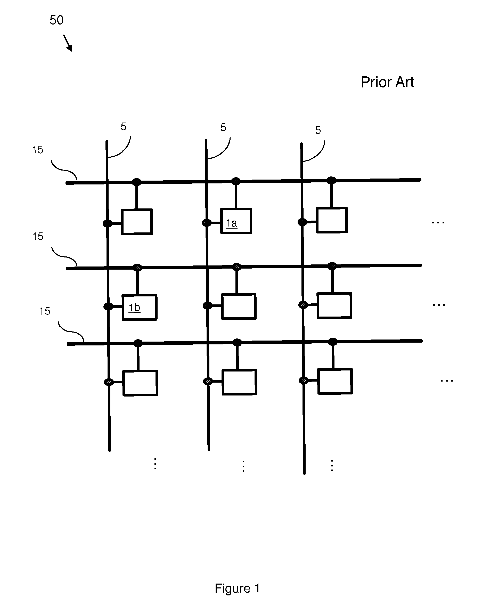
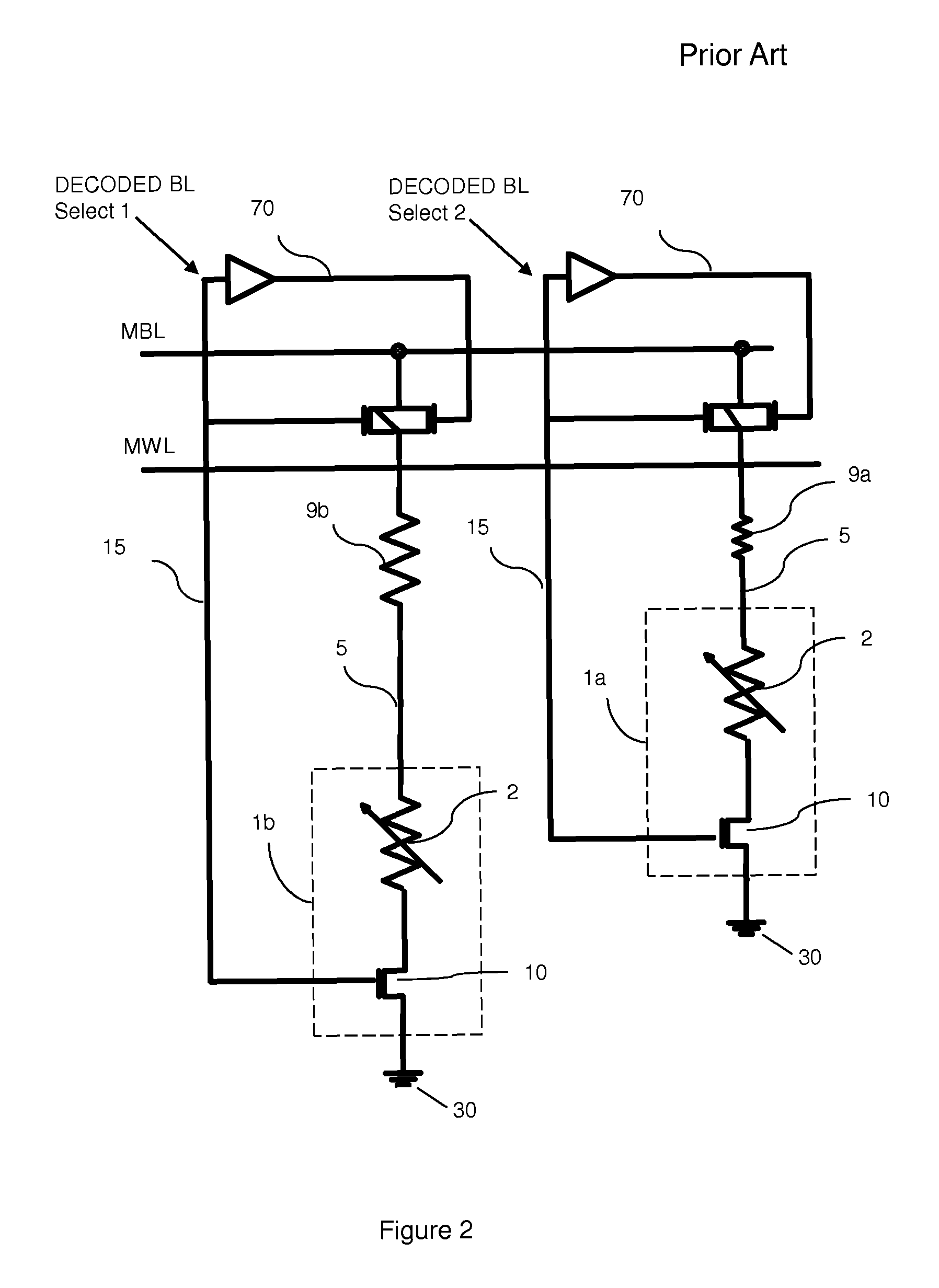
However, one problem associated with such a memory array configuration is that cell current and, hence, power is initially lower than intended.
This lower initial power causes the initial heating rate of the memory cells to lag.
Another problem is that the total energy that is deposited into each phase change element varies depending upon the location of the phase change element in the array.

Method used


Image

  • Balanced and bi-directional bit line paths for memory arrays with programmable memory cells
  • Balanced and bi-directional bit line paths for memory arrays with programmable memory cells
  • Balanced and bi-directional bit line paths for memory arrays with programmable memory cells

Examples


Embodiment Construction

[0033]The embodiments of the invention and the various features and advantageous details thereof are explained more fully with reference to the non-limiting embodiments that are illustrated in the accompanying drawings and detailed in the following description. It should be noted that the features illustrated in the drawings are not necessarily drawn to scale. Descriptions of well-known components and processing techniques are omitted so as to not unnecessarily obscure the embodiments of the invention. The examples used herein are intended merely to facilitate an understanding of ways in which the embodiments of the invention may be practiced and to further enable those of skill in the art to practice the embodiments of the invention. Accordingly, the examples should not be construed as limiting the scope of the embodiments of the invention.

[0034]As mentioned above, the state of a phase change material can be switched through a heating and cooling process which is controlled electri...


PUM


Abstract

Disclosed is a design structure of an improved large scale memory system and, more particularly, an improved memory system that incorporates an array of memory cells that are subjected to minimal location dependent power variations and that, optionally, allows for bi-directional random access of millions of bits. Specifically, the system architecture provides a consistent amount of bit line resistance in the write and read paths to each memory cell in the array, independent of position, in order to minimize variations in power delivery to the cells and, thereby, allow for optimal cell distributions. The system architecture further allows current to pass in either direction through the cells in order to minimize element electro-migration and, thereby, extend memory cell life.

Description

CROSS-REFERENCE TO RELATED APPLICATIONS[0001]This application is related to U.S. application Ser. No. 11 / 539,233 filed Oct. 6, 2007, the complete disclosure of which, in its entirety, is herein incorporated by reference.BACKGROUND[0002]1. Field of the Invention[0003]The embodiments of the invention generally relate to memory arrays incorporating memory cells with programmable memory elements, and, more particularly, to such a memory array with balanced and, optionally, bi-directional bit line paths.[0004]2. Description of the Related Art[0005]Electrical impulses applied to phase change materials can “tune” or “program” them such that they exhibit a desired resistive property to store data. For example, the material can be programmed to store one binary state (e.g., “0”) at a low resistance state and another binary state (e.g., “1”) at a high resistance state. Additionally, such phase change materials can be programmed to multiple different resistance states (e.g., a high resistance ...

Claims


Application Information

Patent Timeline
Patent Type & Authority Patents(United States)
IPC IPC(8): G06F17/50G11C7/02
CPCG11C7/12
Inventor DE BROSSE, JOHN K.LAMOREY, MARK C. H.
Owner IBM CORP
Learn More