Configuration of dilution openings in a turbomachine combustion chamber wall

a technology of combustion chamber wall and dilution opening, which is applied in the direction of combustion process, hot gas positive displacement engine plant, lighting and heating apparatus, etc., can solve the problems of not providing good efficiency, not allowing good intake of dilution air stream, and curvature of folded edges not allowing cooling perforations

Active Publication Date: 2011-02-22
SN DETUDE & DE CONSTR DE MOTEURS DAVIATION S N E C M A
View PDF33 Cites 15 Cited by
  • Summary
  • Abstract
  • Description
  • Claims
  • Application Information

AI Technical Summary

Benefits of technology

[0063]Another advantage of the invention is to enable microperforations 19, 29, 39 for injecting a stream R of cooling air to be installed in the region in the immediate proximity of the edge of the opening 10, 20, 30. In particular, such perforations 19 can be pierced in the downstream edge as close as possible to the dilution opening 10. This allows effective cooling of the region or regions which were most exposed to the formation of hot spots or even burns. Increasing the effectiveness of the cooling R of the walls may make it possible to increase the service life of the combustion chamber 1 and reduce its maintenance frequency.
[0064]The views of FIG. 5 illustrate from various angles of view the shape of a dilution opening 10 formed according to the first embodiment of the invention, in which the dilution opening 10 comprises an upstream edge 11 projecting toward the inside of the chamber, while the downstream edge 12 does not project either toward the inside or toward the outside of the chamber.
[0065]From an inner point of view 5A of the chamber, the opening 10 has a projecting upstream edge and a straight or retreating downstream edge, that is to say that the wall 12 downstream from the opening 10 is flat as far as the edge of the latter. The wall at the downstream edge 12 of the opening is preferably planar or, more generally, rectilinear. From an outer point of view 5B, the opening 10 has a re-entrant upstream edge 11 and a square or smooth downstream edge 12.
[0066]Thus, the downstream edge 12 is substantially nonprominent with respect to the adjacent regions of the wall 3 which immediately surround it and, generally, it is less prominent than the crest of the upstream edge 11.
[0067]The upstream edge 11 of the opening 10 projects toward the inside of the chamber and forms a folded or curved wall portion on the inner side of the wall 3. Preferably, the wall portion of the upstream edge 12 is folded in an oblique direction H-H with respect to the surface of the wall 3 of the chamber. The folded wall portion of the upstream edge 12 preferably extends obliquely at an acute angle (α less than 90°) oriented toward the inside and toward the downstream end of the chamber.
[0068]The dilution opening 10 has an upstream edge 11 in the form of an arch 13 or a dormer window 13 of the “rounded cheek” type, that is to say in the form of a curved-arc vault 13 whose lateral edges 15 are smoothed out progressively until they merge in the plane of the wall 3. The arched vault 13 formed by the upstream edge 11 bears on generatrices H-H which are oblique with respect to the wall 3 and oriented toward the inside and toward the downstream end of the chamber. The aperture of the opening 10 is oriented obliquely toward the inside and toward the downstream end with respect to the wall 3 of the chamber. The downstream edge 12 of the opening 10, that is to say approximately half the circumference on the downstream side of the opening 10, does not have any protrusion either on the inner side or on the outer side.

Problems solved by technology

These dilution openings 8′ with straight edges according to the prior art have the disadvantages of not allowing good intake of the dilution air stream D and of not providing good efficiency.
Another disadvantage of the dilution openings 8′ with “bent-over edges” is that the curvature of the folded edges does not allow cooling perforations to be pierced in the immediate vicinity of the opening 8 and specifically in the regions exposed to the formation of hot spots or burns, which would require effective cooling.

Method used


Image

  • Configuration of dilution openings in a turbomachine combustion chamber wall
  • Configuration of dilution openings in a turbomachine combustion chamber wall
  • Configuration of dilution openings in a turbomachine combustion chamber wall

Examples


first embodiment

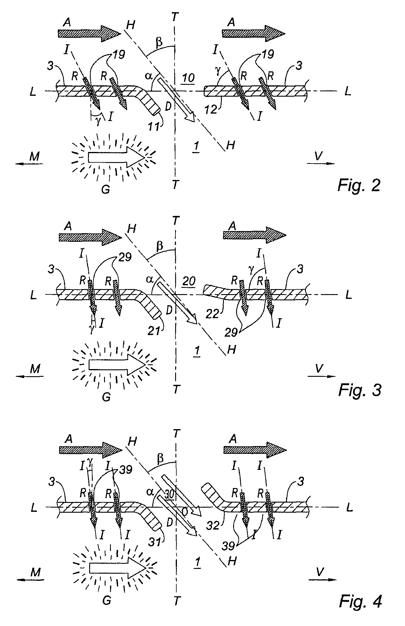
[0050] schematically represented in FIG. 2, the downstream periphery 12 of the opening 10 has a square edge, that is to say a nonprojecting straight edge 12, inscribed in the continuation of the side wall 3 (planar or rectilinear edge).

second embodiment

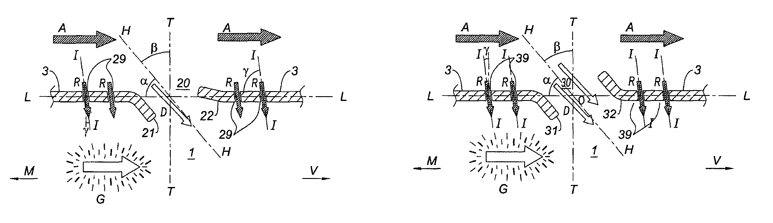
[0051] schematically represented in FIG. 3, the opening 20 has a downstream edge 22 projecting slightly toward the outside of the chamber 1, the downstream edge 22 (turned toward the outside) projecting less than the upstream edge 21 (turned toward the inside).

third embodiment

[0052] schematically represented in FIG. 4, the opening 30 has a downstream edge 32 projecting toward the outside of the chamber 1, the downstream edge 32 here projecting substantially to the same extent toward the outside as the upstream edge 31 is projecting toward the inside 1. In this case, the edges 31 and 32 of the opening can be symmetrical with respect to a central point O of the opening 30 without nevertheless being symmetrical with respect to a plane T-T extending transversely to the wall 3.

[0053]One advantage of an opening according to the invention having a downstream edge 22 or 32 projecting toward the outside is that of being able to capture and divert the stream A of fresh air which sweeps along the outside of the walls 3 of the chamber 1 and thus to accentuate the fresh air intake stream D into the chamber 1. Depending on how much the downstream edge 22 or 32 protrudes toward the outside, this accentuation will be marked to a greater or lesser degree.

[0054]According ...


PUM


Abstract

An annular combustion chamber of a turbomachine is provided. The combustion chamber includes an end wall provided at an upstream end of the chamber and side walls extending longitudinally from the end wall to an orifice for discharging a stream of combustion gases provided at a downstream end of the chamber. The side walls includes at least one row of openings for the intake of air for diluting the stream of combustion gases. At least one dilution opening has an upstream edge which projects toward the inside of the chamber and a downstream edge which projects toward the outside of the chamber and is asymmetric to the upstream edge with respect to a plane extending transversely to the wall. An aperture of the opening having an axis oriented in an oblique direction with respect to the wall. This direction being oriented toward the inside and toward the downstream end of the chamber.

Description

1—TECHNICAL FIELD AND BACKGROUND OF THE INVENTION[0001]The invention relates to the field of combustion chambers of turbine engines and, more specifically, to the configuration of the dilution air intake openings and the cooling air passage perforations formed in the walls of the flame tube or in any combustion chamber wall element.[0002]FIG. 1B shows a view in axial section of a turbomachine combustion chamber 1 according to the prior art, as described in patent document EP-A-0 743 490 in the name of the applicant.[0003]The combustion chamber 1 is formed by two concentric tubular side walls 3, constituting a flame tube (extending in the longitudinal direction L-L of the chamber, parallel here to the axis X-X of the turbomachine). The chamber is closed at one end, the upstream end M, by an annular end wall 4 at which are located fuel injectors 6 and oxidizer air inlets 7, the combustion of the fuel and oxidizer generating a stream of combustion gases. The chamber is terminated at th...

Claims


Application Information

Patent Timeline
Patent Type & Authority Patents(United States)
IPC IPC(8): F02C1/00F02G3/00
CPCF23R3/06
Inventor BIEBEL, ROMAINDAGUENET, LUC HENRI CLAUDESANDELIS, DENIS JEAN MAURICE
Owner SN DETUDE & DE CONSTR DE MOTEURS DAVIATION S N E C M A
Why Eureka
Try Eureka