
Compact crossbow with improved efficiency

a crossbow and efficiency technology, applied in the field of crossbow type devices, can solve the problems of short power stroke, inconvenient use, and inconvenient use,

Inactive Publication Date: 2011-02-22
COLLEY DAVID E
View PDF29 Cites 107 Cited by
  • Summary
  • Abstract
  • Description
  • Claims
  • Application Information

AI Technical Summary

Benefits of technology

The crossover bow achieves superior performance and accuracy at lower draw weights, making it more versatile and usable for a wider range of archers, with adjustable features for comfort and maintenance without the need for a bow-press, and supports arrows efficiently without the friction and flexure issues of conventional crossbows.

Problems solved by technology

In reality, however, even in the case of the more modern versions of the crossbow where compound bow type limb mounted cams are used in order to increase the stored energy, this is not the case.
The dimensional limitations of the conventional crossbow restrict the power stroke to a very short length as compared to a bow.
Thus the crossbow is, comparatively, a much less efficient device than the bow.
Subsequently, the requirement of an extremely high draw weight, in many cases, makes the crossbow either undesirable or even unusable for a number of archers due to the difficulty encountered in drawing and cocking the device.
Although a number of unique devices have been developed to assist in drawing and cocking the heavy pull weight of a crossbow, such devices are normally cumbersome, elaborate, tedious, or equally uncomfortable and inconvenient to use.
However, using limb mounted cams on a crossbow in the same manner that they are used on a conventional compound bow introduces the same undesirable conditions such as limb twist, cam lean, and asymmetrical loading to the projectile as well as various components that occur with conventional compound bow design.
However, although the draw weights used are substantially in excess of that of a compound bow, it is usually impractical to design the components of a compound type crossbow such that they would withstand the somewhat higher forces that may be used with traditional, re-curve limb type crossbows.
Of course, the higher poundage of the traditional crossbow that is dictated by the short power stroke, again, makes such a configuration undesirable in many cases.
While this means of supporting the bolt in a crossbow is necessary, it also lends to the inefficiency of the device to a degree in that a lengthy duration of contact between the bolt and the barrel is experienced during launch.

Method used


Image

  • Compact crossbow with improved efficiency
  • Compact crossbow with improved efficiency
  • Compact crossbow with improved efficiency

Examples


Embodiment Construction

)

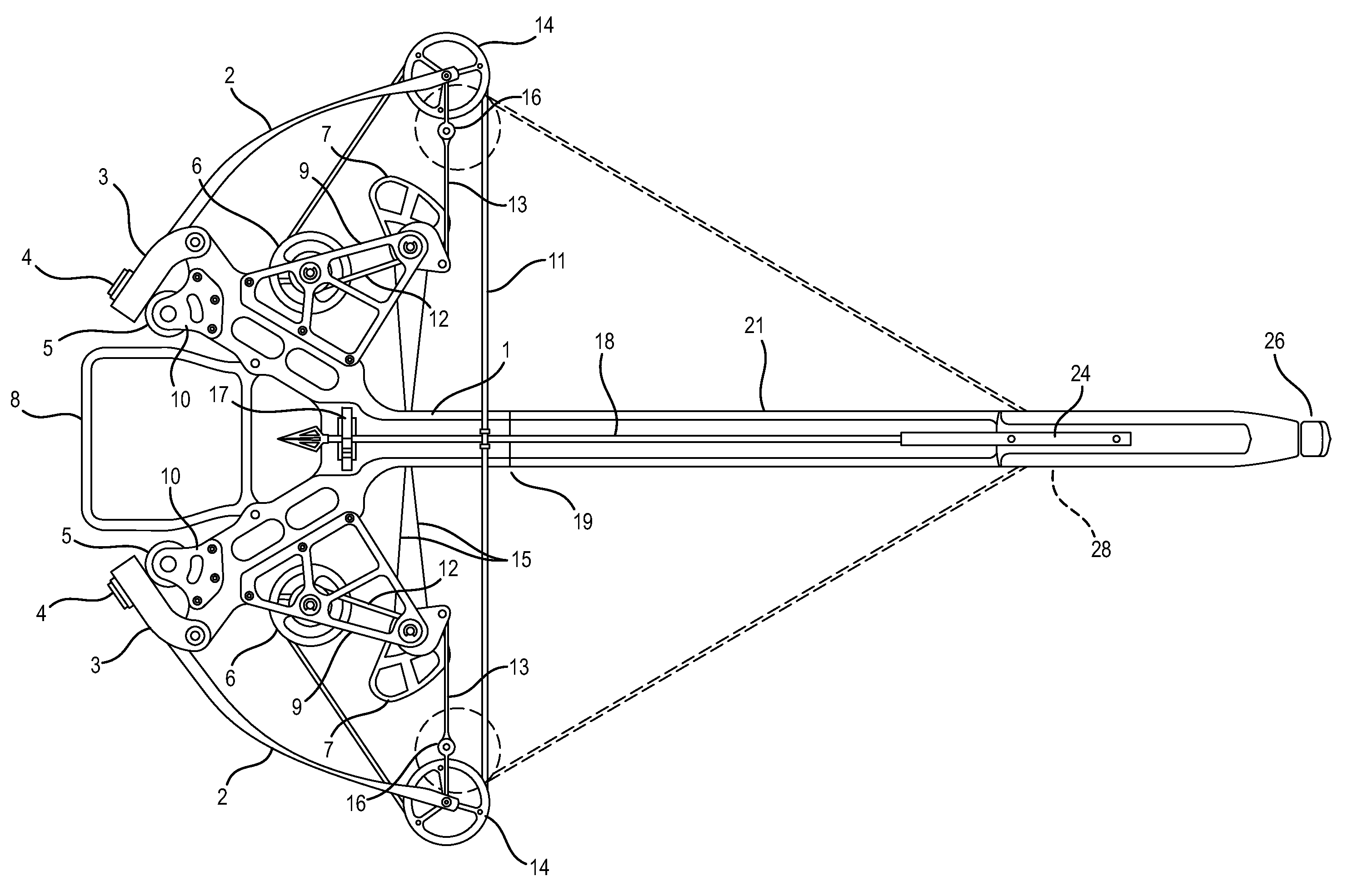
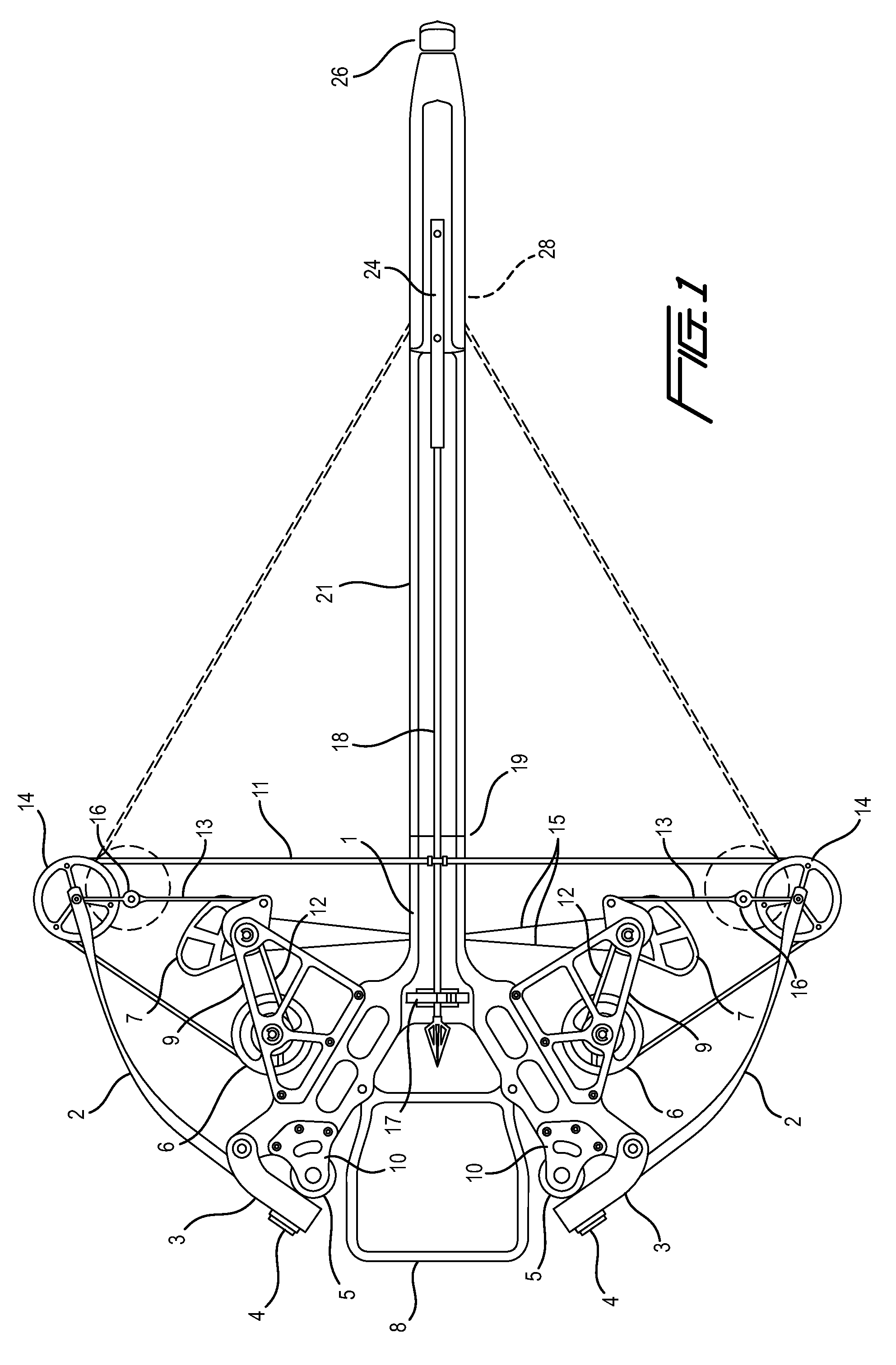
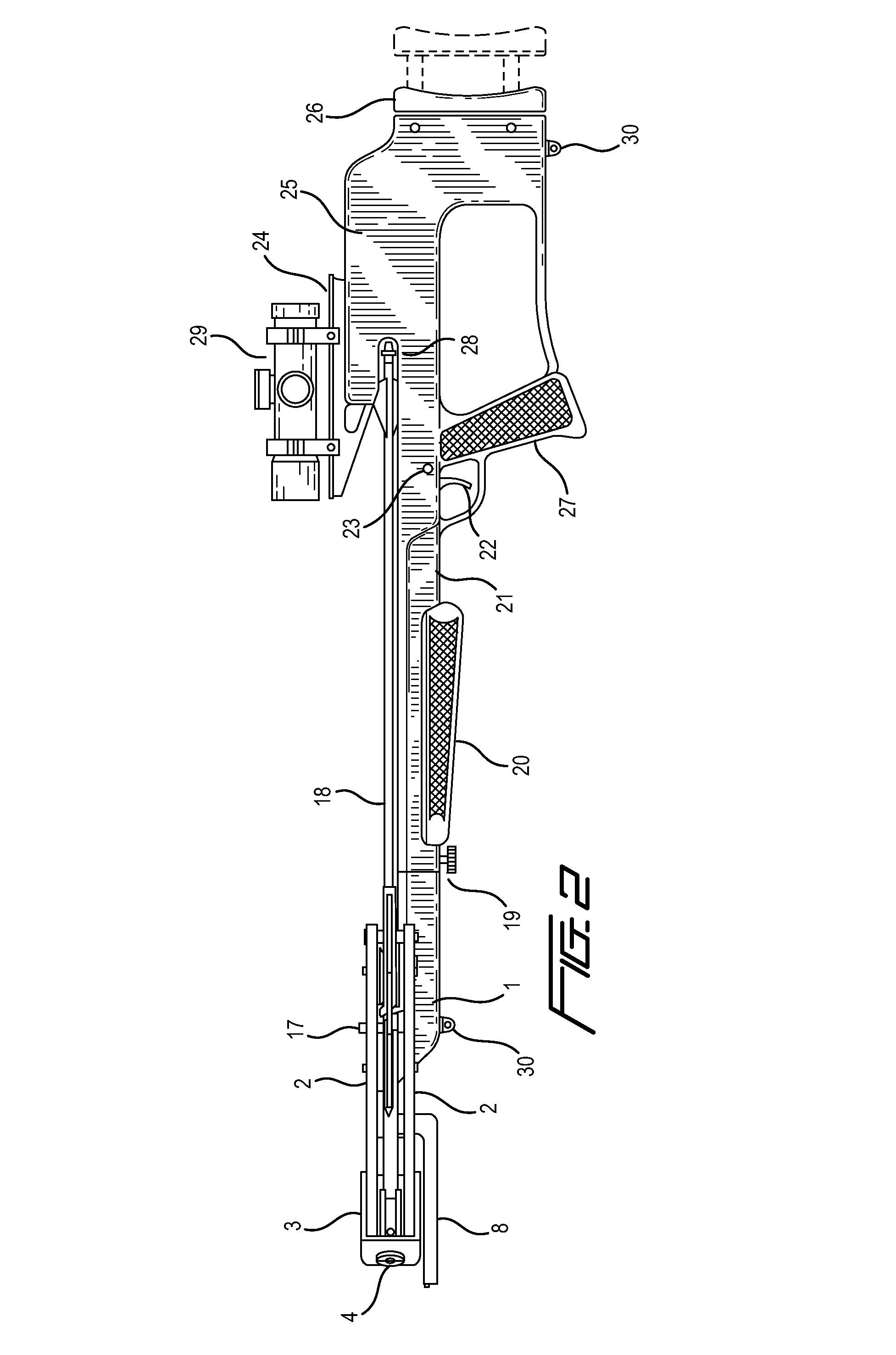
[0027]As shown in FIG. 1, a bow embodying the invention comprises a riser 1 which supports at either end a limb 2 whose inner end is pivotally seated in a limb pocket 3 at the end of the riser.

[0028]The riser, as seen in FIG. 1, is symmetrical. Its opposite wings support respective identical bowstring tensioning mechanisms. Each tensioning mechanism includes an adjustment bolt 4 installed in a limb bolt anchor 5. Each anchor is supported by a respective front pylon 10 formed from a first pair of plates, one on either side of the riser. The rear pylons 9 are discussed further below.

[0029]The angular position of each pocket, and thus its limb, can be adjusted by turning the adjustment bolt 4. The bolt is sufficiently long to maintain adequate thread engagement over the range of from no limb preload to the maximum permissible limb preload. This way, the bolts can be safely unscrewed until the limbs are fully relaxed, permitting disassembly of the bow without the danger of unexpected e...


PUM


Abstract

A “cross-over” compound crossbow includes a stock and barrel assembly attached to a horizontally mounted compound bow. The compound bow component is similar to that of U.S. Pat. No. 7,047,958 and includes an alternative arrow support system to achieve higher arrow velocity at a reduced draw weight. The crossover compound bow also provides draw weight adjustability and positive cam synchronization.

Description

[0001]This application claims benefit of provisional patent application Ser. No. 60 / 911,717, filed Apr. 13, 2007.BACKGROUND OF THE INVENTION[0002]This invention relates generally to archery equipment and more specifically to crossbow type devices.[0003]The crossbow is an ancient weapon that has remained relatively unchanged over the centuries and up to modern times. The crossbow has a number of advantages over the traditional or conventional archery bow configuration. One such advantage is that the crossbow uses a stock that allows the device to be supported, aimed and fired using a trigger much in the same manner as a rifle. Yet another advantage that a crossbow provides is that the bowstring is mechanically held in the fully drawn position eliminating the need for the archer to physically hold the fully drawn bowstring while aiming and shooting the device. These two advantages are among the primary reasons that the crossbow is sometimes chosen over the traditional bow configuratio...

Claims


Application Information

Patent Timeline
Patent Type & Authority Patents(United States)
IPC IPC(8): F41B5/12
CPCF41B5/105F41B5/123
Inventor COLLEY, DAVID E.
Owner COLLEY DAVID E
Learn More