Outdoor light with positionable solar collector

a solar collector and outdoor light technology, applied in the direction of lighting support devices, ways, and with built-in power, can solve the problems of discoloring the solar cell, affecting the purpose of the lighting system, and requiring excessive installation of the underground cable, so as to optimize the exposure of the outdoor light, minimize the visual impact, and enhance the visibility

Inactive Publication Date: 2011-02-22
ALLSOP
View PDF35 Cites 9 Cited by
  • Summary
  • Abstract
  • Description
  • Claims
  • Application Information

AI Technical Summary

Benefits of technology

[0008]The lighting element assembly has a diffuser positioned over the lighting element to diffuse the light therefrom. In one embodiment, the diffuser is made of cracked glass to enhance visibility thereof. A support adapter secures the diffuser and lighting element to the support and has a diffuser receptacle, a lighting element seat, and a support receiver sleeve. The diffuser receptacle receives a portion of the diffuser to secure the diffuser to the support. In some embodiments, a threaded attachment secured to the diffuser directly engages a threaded region on the receptacle. Apertures may be formed in the diffuser receptacle to enable drainage of moisture built up within the diffuser.
[0009]The lighting element is positioned within the lighting element seat, which is located within the diffuser receptacle. The lighting element seat opens into the support receiver sleeve and provides a channel receiving a wire that extends from the collector unit to the lighting element. The support receiver sleeve receives the end of the support to secure the support adapter thereto. In some embodiments, a lighting element shield may be positioned over the lighting element and lighting element seat to protect the lighting element from moisture.
[0010]The lighting system may include separate supports for the lighting element assembly and the collector unit. In one embodiment, the collector unit includes a clip-on clamp, which allows the collector unit to be removably secured to its support. If desired, this allows the collector unit to be removed from its support and attached to another support, such as the support for the lighting element assembly. Advantages of this arrangement include the ability to position the collector unit to optimize its exposure to sunlight and minimize its visual impact in the applicable setting, for example, by inserting its support further into the ground or soil.

Problems solved by technology

However, underground cables require excessive labor to install and interfere with gardening and landscaping efforts, as they are dug up by tilling, planting, and the like.
However, prior systems interfere with the purpose of the lighting system, which is principally aesthetic.
As time passes, mineral deposits and fading often discolor the solar cell.
Ultimately, the solar cell distracts from any ornamental qualities the lighting system was designed to have.

Method used


Image

  • Outdoor light with positionable solar collector
  • Outdoor light with positionable solar collector
  • Outdoor light with positionable solar collector

Examples


Embodiment Construction

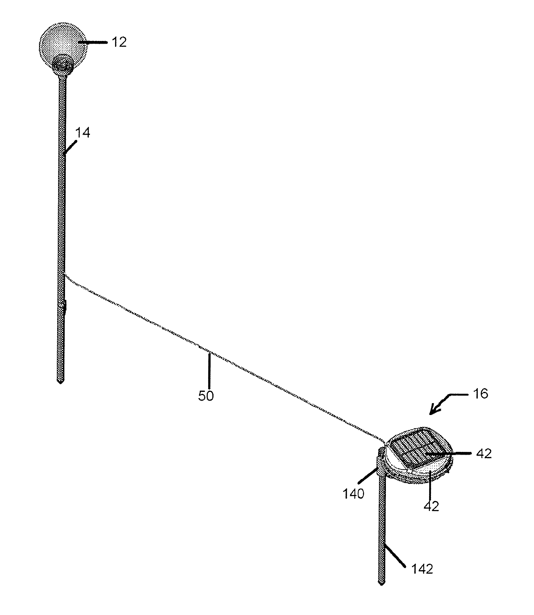
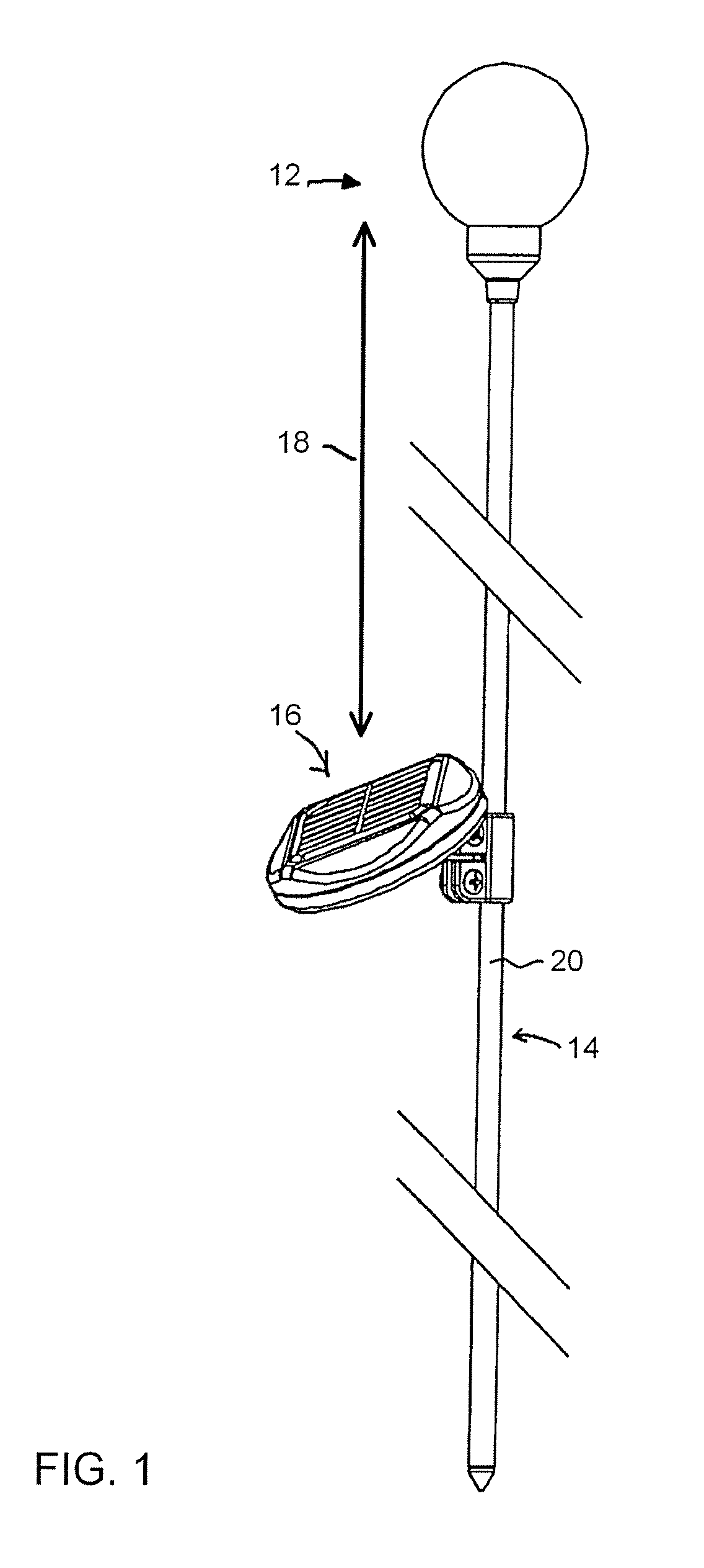
[0025]Referring to FIG. 1, a lighting system 10 may include a lighting element assembly 12, a support 14, and a collector unit 16. The lighting element assembly 12 typically includes a light producing means such as an incandescent lamp or LED. The lighting element assembly 12 secures near the upper end of the support 14 a distance 18 from the collector unit 16. In typical uses, the collector unit 16 will be positioned at or below the upper boundary of foliage and the like in order to minimize its visual impact. The collector unit 16 typically contains a solar cell and a battery, or like means, for collecting and storing solar energy during daylight hours. The solar cell and battery may be integrated in the collector unit 16 or may secure separately to the support 14. Wiring (not shown) connects the lighting element assembly 12 to the collector unit 16.

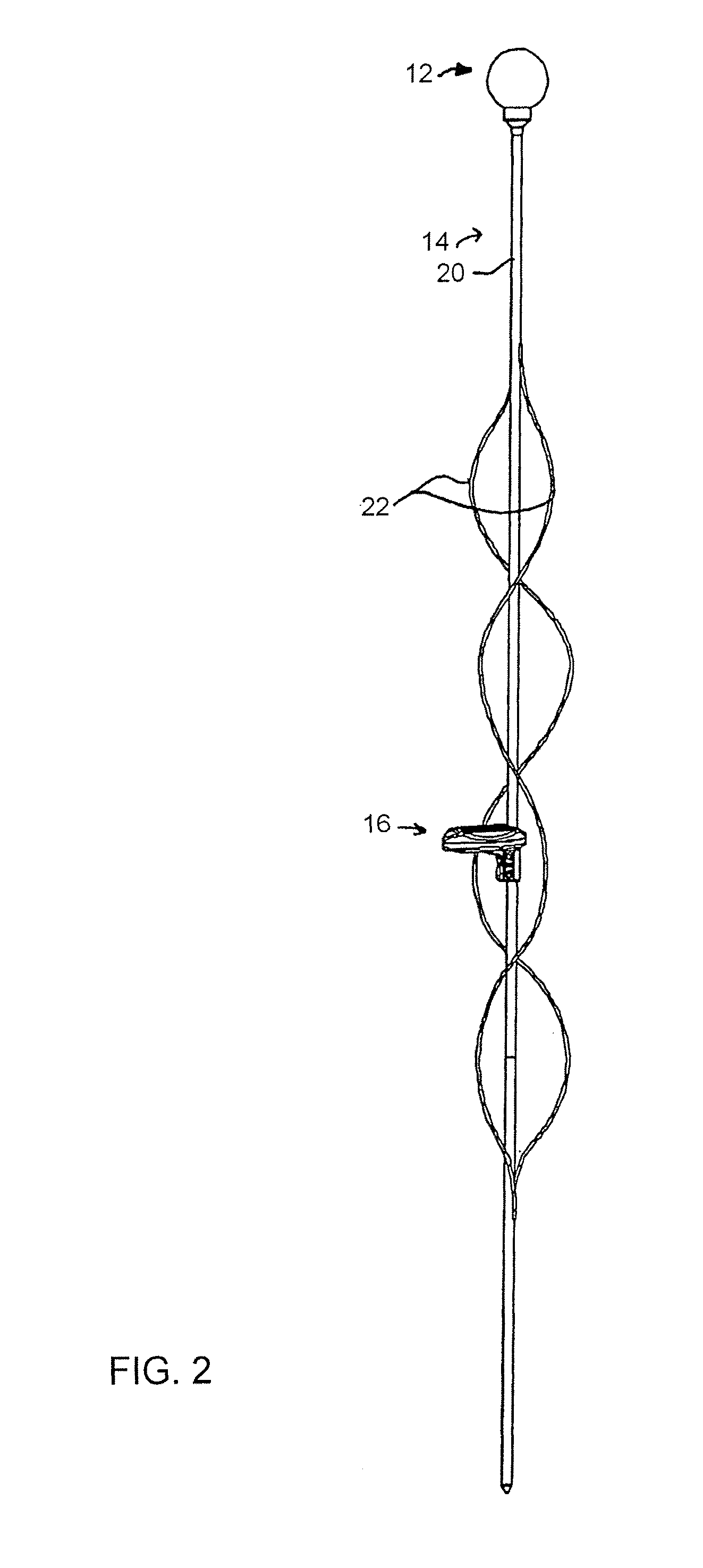
[0026]The support 14 may be straight, curved, or sloped, or have a non-deterministic ornamental shape. In the illustrated embodiment,...


PUM


Abstract

A solar powered lighting system provides a lighting element assembly having a lighting element and a diffuser that secures near the upper end of a support. A collector unit contains a solar cell and a coupler such as a clip-on clamp which allows the collector unit to be selectively attached to a desired support. The lighting system includes a battery electrically coupled to the solar cell of the collector unit and to the lighting element assembly using a wire such that the portion of the wire that extends from the collector unit to the lighting element assembly is of sufficient length to allow the collector unit to be selectively positioned on or remotely from the support.

Description

PRIORITY CLAIM[0001]This application is a continuation-in-part of U.S. patent application Ser. No. 11 / 133,163 filed May 18, 2005, the disclosure of which is incorporated herein by reference in its entirety.FIELD OF THE INVENTION[0002]This invention relates generally to outdoor lighting apparatus, and, more specifically, to solar powered outdoor lighting apparatus.BACKGROUND OF THE INVENTION[0003]Outdoor lighting can provide an important accent to any yard or garden. A gardener or landscaper may strategically place many lights in a landscape to illuminate walkways and to otherwise enhance the appearance of the landscape at night. Some lighting systems are designed to simply provide light while in others the lights themselves serve ornamental purposes even when they are not illuminated.[0004]In many prior systems, lights are wired directly to an adjacent residence through underground power cables. However, underground cables require excessive labor to install and interfere with garden...

Claims


Application Information

Patent Timeline
Patent Type & Authority Patents(United States)
IPC IPC(8): F21L4/08F21S8/08
CPCF21S8/081F21S8/088F21S9/035F21V17/02F21S4/10F21V21/0824F21V3/04F21V21/08F21V21/116F21V23/0442F21W2131/00F21W2131/10Y02B20/72F21Y2115/10
Inventor ALLSOP, JAMES D.CLAUSEN, EIVINDALLSOP, JAMEY J.
Owner ALLSOP
Why Eureka
Try Eureka