Compact filter

a filter and compact technology, applied in the field of compact filters, to achieve the effect of minimal flow resistance, minimal sensitivity, and high flow deflection efficiency

Active Publication Date: 2011-02-22
MANN HUMMEL GMBH
View PDF9 Cites 3 Cited by
  • Summary
  • Abstract
  • Description
  • Claims
  • Application Information

AI Technical Summary

Benefits of technology

[0007]A compact filter, particularly a compact air filter for motor vehicles, is proposed that has a compact filter element that is arranged in a filter housing so as to be exchangeable wherein the compact filter element comprises a filter body with longitudinal axis. The compact filter element has at the unfiltered air side a baffle element that can be removed together with the filter element from the filter housing and the baffle element has at least one baffle surface that is slanted relative to the longitudinal axis. The baffle element can be clipped on the filter body loosely or with clamping action and is preferably fixedly connected thereto, for example, by direct injection molding onto a plastic part that is connected to the element. It can also be connected by gluing, by laying in foam or the like. By a suitable design of the baffle element the incoming dust-laden air flow is subjected to deflection at least approximately in a direction that is parallel to the longitudinal axis of the filter body or its air channels. The dust particles entrained by the air flow are forced to follow this deflection. In this way, a more uniform dust loading of the filter body is achieved. The useful service life is increased. The attachment of the baffle element on the filter body exerts a stabilizing effect on the filter body. It can be handled more easily when servicing the filter. The installation and removal are simplified. Moreover, an exact positional alignment of the baffle element relative to the filter body is ensured so that precisely defined intake conditions with uniform dust loading will be permanently maintained even after the compact filter element has been changed. The user is forced to change the baffle element together with the filter body so that damage, wear or excessive soiling cannot remain unnoticed.
[0008]In an advantageous further embodiment, an end of the baffle element at the downstream side adjoins an end face of the filter body at the intake side approximately in the area of its longitudinal axis wherein an upstream end of the baffle element is positioned approximately at a position of the intake surface area of the filter housing that is to be defined. In this way, the incoming air flow is divided into two partial streams. The entrained dust quantity is also divided in the same way into two partial quantities and is uniformly distributed across two partial surface areas of the filter body at least in approximation. Essentially the same can hold true for a larger number of baffle elements that divide the incoming air flow and the entrained dust quantity into a corresponding number of approximately identically sized partial streams and distribute it onto approximately same size surface areas of the filter body. The uniformity of the dust loading of the filter body is significantly improved even in the case of intake conditions with distinctive asymmetry. However, the distribution into partial streams can also be done so as to be non-uniform.
[0009]In a preferred embodiment, the baffle element is a curved plate. At high efficiency of the flow deflection a minimal flow resistance with minimal effect on the total flow resistance of the compact air filter results. The configuration as a curved plate leads to a minimal sensitivity in regard to abrasion caused by impacting dust particles.
[0010]In an expedient alternative, the baffle element has two baffle surfaces positioned at a spacing to one another; their spacing in the flow direction of the medium to be filtered narrows from an intake spacing to a minimal spacing. In addition to the afore described deflection function this arrangement also has an acoustic function. The spacing that narrows in the flow direction acts as a muffler for intake noise. In an expedient further embodiment, the spacing of the baffle surfaces in the flow direction of the medium widens from the minimal spacing to an the exit spacing. In this way, a diffuser is formed that, while maintaining the sound damping function, compensates the pressure loss in the area of the minimal spacing at least approximately. The flow resistance is minimized.
[0011]The arrangement according to the invention can be used effectively in a plurality of intake flow conditions of the compact filter. Preferred is a use in arrangements in which the intake opening of the filter housing with its center axis has a lateral displacement and / or angular displacement relative to the longitudinal axis of the filter body. In particular, the base surface of the filter body has a narrow side and a long side wherein the intake opening is arranged in the area of the narrow side. This provides a distinct effectiveness of the baffle element with which in particular a pronounced tendency for non-uniform dust loading is compensated with high efficiency.

Problems solved by technology

However, the distribution into partial streams can also be done so as to be non-uniform.

Method used


Image

  • Compact filter
  • Compact filter
  • Compact filter

Examples


Embodiment Construction

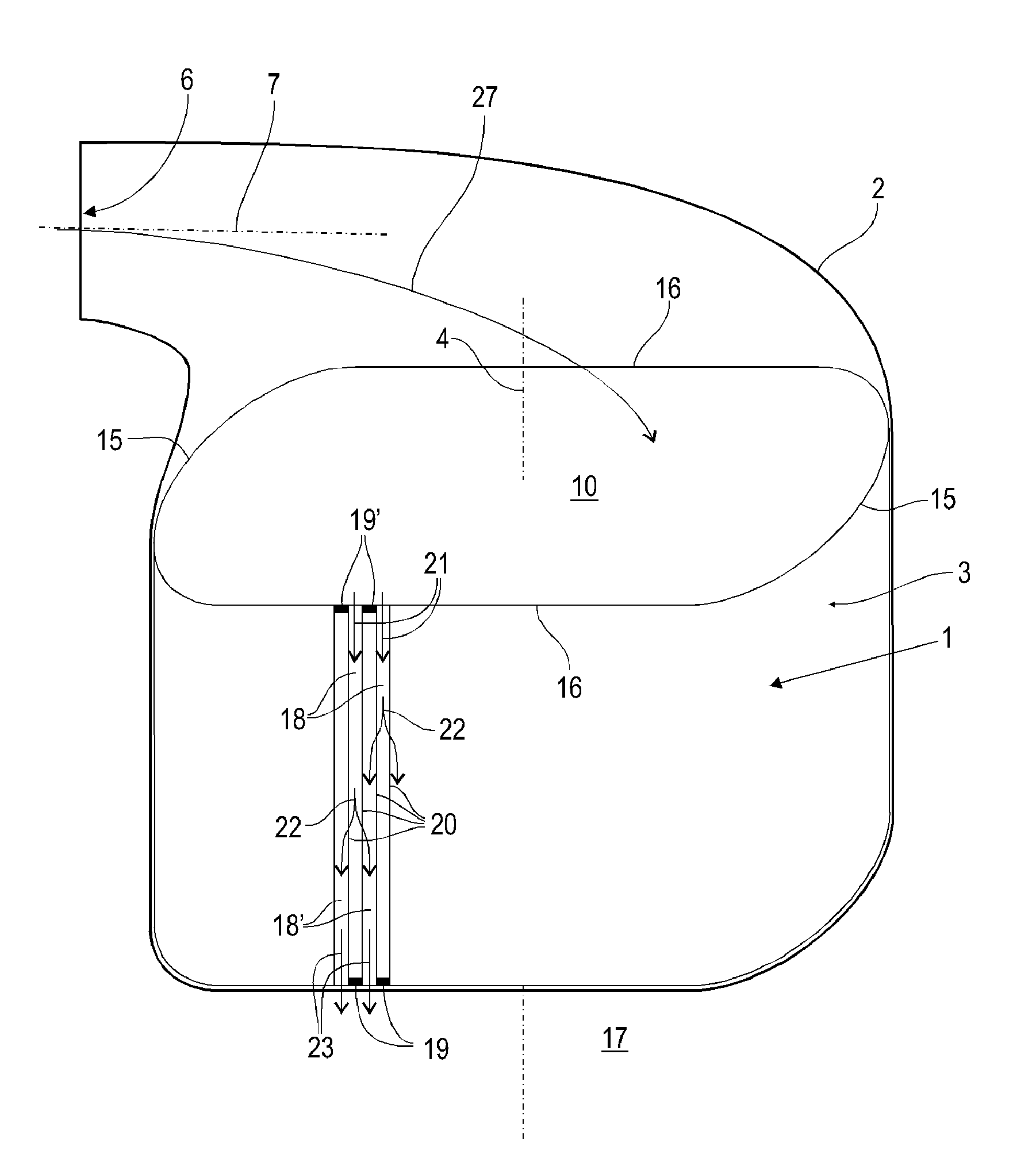
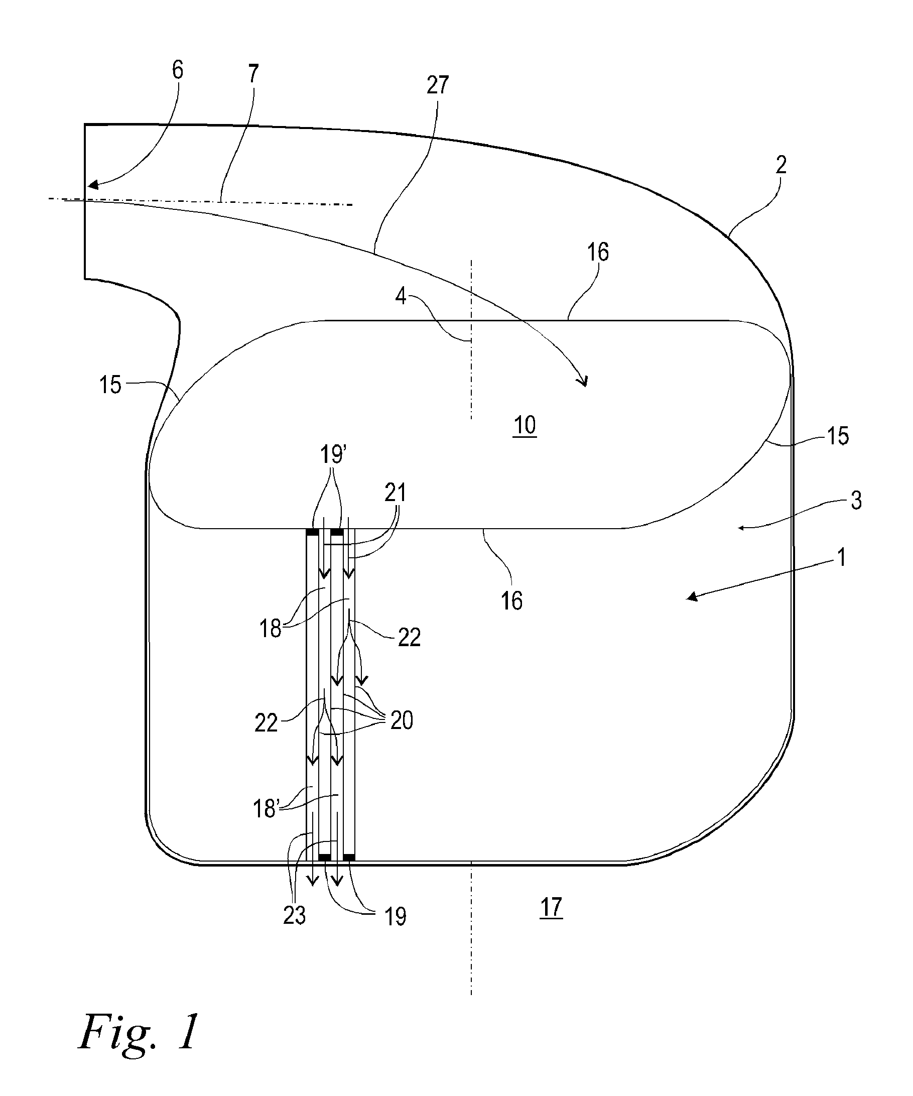
[0016]FIG. 1 shows in a perspective illustration a compact filter that is designed as a compact air filter for a motor vehicle. However, other applications particularly in the area of gas and air filtration are conceivable. The compact filter comprises a compact filter element 1 with a filter body 3 and a schematically indicated filter housing 2. The filter housing 2 can be separated in a way not illustrated in detail in order to be able to change the compact filter element 1 at certain service intervals. The filter body 3 is comprised of filter paper wherein alternatingly flat and undulated filter paper webs are stacked on one another. The filter body 3 is formed by winding, stacking or folding such semi-finished products. The alternatingly adjoining undulated and flat filter paper webs generate as a result of their layer sequence a plurality of gas channels 18, 18′ that extend parallel to a longitudinal axis 4 of the filter body 3. The filter body 3 is almost completely penetrated...


PUM

PropertyMeasurementUnit
areaaaaaaaaaaa
lateral displacementaaaaaaaaaa
angular displacementaaaaaaaaaa

Abstract

A compact filter has a filter housing and a compact filter element that is arranged in the filter housing, wherein the filter element is exchangeable. The compact filter element has a filter body having a longitudinal axis. The compact filter element has an unfiltered air side and a filtered air side. A baffle element is arranged at the unfiltered air side of the compact filter element. The baffle element is removable together with the filter element from the filter housing and has at least one baffle surface that is slanted relative to the longitudinal axis.

Description

CROSS REFERENCE TO RELATED APPLICATIONS[0001]This application claims priority to Federal Republic of Germany patent application no. DE 202007010601.7, filed Jul. 27, 2007, the entire disclosure of which is incorporated herein by reference.BACKGROUND OF THE INVENTION[0002]The invention relates to a compact filter, in particular, a compact air filter for motor vehicles. The compact filter comprises a compact filter element that is arranged in a filter housing so as to be exchangeable, wherein the compact filter element comprises a filter body having a longitudinal axis.[0003]For filtering air, so-called compact filters are widely used that are in particular comprised of layered filter paper. An undulated filter paper web is applied to a flat filter paper web. The semi-finished product produced in this way is wound to a filter body or stacked so that a plurality of parallel extending gas channels will result. These gas channels are alternately closed off by plugs. Incoming air flows fr...

Claims


Application Information

Patent Timeline
Patent Type & Authority Patents(United States)
IPC IPC(8): B01D50/00
CPCB01D46/0043B01D46/525
Inventor FREISINGER, JUERGENRIEGER, MARIO
Owner MANN HUMMEL GMBH
Why Eureka
Try Eureka