Magnetically biased magnetopropant and pump

a magnetopropant and pump technology, applied in the field of magnetostrictive materials, can solve the problems of difficult to supply a controllable magnetic field in a geologic formation, not always practical to supply a controllable magnetic field of sufficient strength, etc., and achieve the effect of enhancing the magnetostrictive behavior of the magnetopropant and expanding the capabilities of magnetostrictive materials

Inactive Publication Date: 2011-02-22
KNOBLOCH CHARLES SARON
View PDF39 Cites 12 Cited by
  • Summary
  • Abstract
  • Description
  • Claims
  • Application Information

AI Technical Summary

Benefits of technology

[0005]What I am about to describe here is a new way to extend the capabilities of magnetostrictive materials, specifically magnetopropants. Magnetic particles of significant magnetic field strength are added to the propant materials. For instance, a cobalt / nickel ferro-magnetic alloy. These magnetic particles act to provide magnetic bias, or additional magnetic bias, to assist in actuating the magnetopropant. To further enhance the magnetostrictive behavior of the magnetopropant, a vibrational field is introduced. For example, the vibrational field may be created by acoustic stimulation or a pressure wave, such that a relative movement is induced between the magnetic particles and the magnetopropant. The relative movement varies the actuation of the magnetostrictive behavior, causing the desired magenetopropant effect.

Problems solved by technology

It is not always practical to supply a controllable magnetic field of sufficient strength at locations where it is desired to actuate the magnetostrictive material.
For instance, it is difficult to supply a controllable magnetic field in a geologic formation at a distance far from a well bore.

Method used


Image

  • Magnetically biased magnetopropant and pump
  • Magnetically biased magnetopropant and pump

Examples


Embodiment Construction

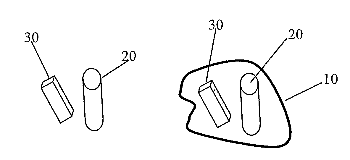
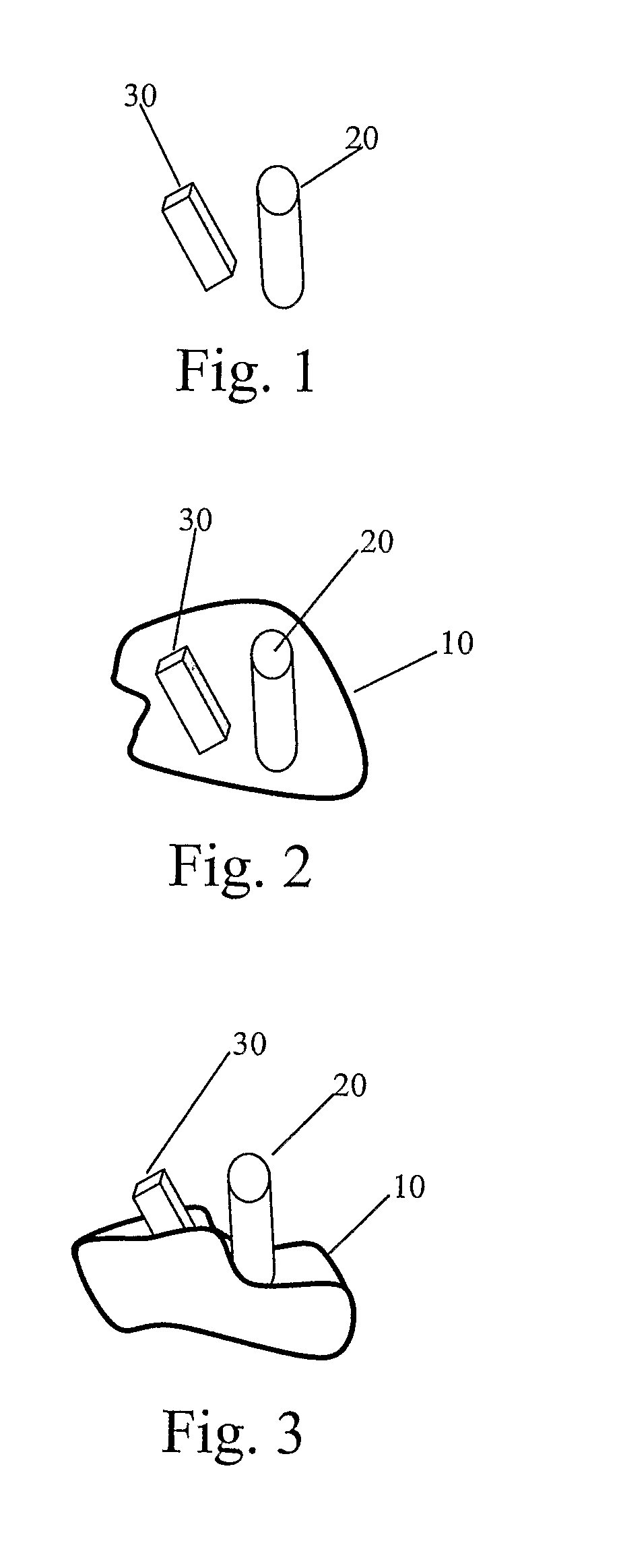
[0031]Each of FIGS. 1-3 illustrates the pressure sensitive magnetopropant used to produce various aspects of the present invention, though these particular embodiments are illustrated and described herein only for exemplary purposes. Moreover, variations of the system and methods of utilizing the same will become apparent to those of ordinary skill in the relevant structural and mechanical arts upon reading the following disclosure. Thus, the present invention is not to be considered limited to only the structures, systems, and methods described herein.

[0032]FIG. 1 illustrates a mixture of magnetopropant 20 particles and a magnetic biasing material, magnetic particle 30. This represents one means for disposing a magnetic biasing material in movable proximity to the magnetopropant. In this configuration, there is no fixed spatial relationship between magnetopropant particles and magnetic particles. The mixture of particles may be embedded or otherwise added to a porous medium. The ra...


PUM

PropertyMeasurementUnit
magnetostrictiveaaaaaaaaaa
mechanical vibrational forceaaaaaaaaaa
pore volumeaaaaaaaaaa

Abstract

Provided is a system and method for enabling pressure or acoustic waves to induce magnetostrictive volume or shape change, providing greater control over magnetopropants. A coating material and the spacing between a magnetopropant and a magnetic particle are selected such that a certain pressure causes change in the relative distance of magnetopropant and magnetic particle, thereby changing the amount of magnetostriction. The coating material, magnetopropant, and magnetic particle are assembled to form a pressure sensitive magnetopropant. Given this structure, changes in pressure will cause a fluctuation of the amount of magnetostriction. In a pore space environment, this causes a change in pore space with resulting change in permeability and, hence, changes in fluid flow.

Description

CROSS REFERENCE TO RELATED APPLICATIONS[0001]This application is the National Stage of International Application No. PCT / US2006 / 016761, filed May 2, 2006, which claims the benefit of U.S. Provisional Patent Application No. 60 / 677,229, filed May 2, 2005 and the benefit of U.S. Provisional Patent Application No. 60 / 677,250, filed May 2, 2005. International Application No. PCT / US2006 / 016611, filed May 2, 2006, further claims the benefit of U.S. Provisional Patent Application No. 60 / 677,229, filed May 2, 2005 and the benefit of U.S. Provisional Patent Application No. 60 / 677,250, filed May 2, 2005. A U.S. National Stage Application of International Application No. PCT / US2006 / 016611 is being filed on the same date as this application. U.S. application Ser. No. 11 / 278,669, filed Apr. 4, 2006, which claims the benefit of U.S. Provisional Patent Application No. 60 / 668,135 filed Apr. 4, 2005, has a common inventor.FIELD OF THE INVENTION[0002]The present invention relates generally to magnetos...

Claims


Application Information

Patent Timeline
Patent Type & Authority Patents(United States)
IPC IPC(8): H01F7/00H01H55/00H01L41/00H02N2/00H04R15/00
CPCG01V1/005H01L41/06H01L41/12H04B11/00H10N35/80H10N35/00
Inventor KNOBLOCH, CHARLES SARON
Owner KNOBLOCH CHARLES SARON
Why Eureka
Try Eureka