Solenoid valve of shock absorber

a technology of solenoid valve and shock absorber, which is applied in the direction of valve operating means/release devices, shock absorbers, suspensions, etc., can solve the problems of time and effort consumed in assembling the disc valve, and the structure of the disc valve is complicated

Active Publication Date: 2011-03-01
HL MANDO CORP
View PDF18 Cites 20 Cited by
  • Summary
  • Abstract
  • Description
  • Claims
  • Application Information

AI Technical Summary

Benefits of technology

[0038]Although the present invention have been described with a specified embodiment, it will be apparent to those skilled in the art that various modifications, changes and variations can be made thereto within the scope of the present invention and the appended claims. Therefore, the aforementioned descriptions and the accompanying drawings should be construed as not limiting the technical spirit of the present invention but illustrating the present invention.

Problems solved by technology

However, the disc valve for varying damping force of the aforementioned conventional shock absorber comprises a plurality of discs, a ring, a retainer and the like having various sizes and shapes, so that a structure of the disc valve is complicated.
In addition, there are a large number of parts of the disc valve, so that the time and effort is enormously consumed in assembling the disc valve.

Method used


Image

  • Solenoid valve of shock absorber
  • Solenoid valve of shock absorber
  • Solenoid valve of shock absorber

Examples


Embodiment Construction

[0016]Hereinafter, an embodiment of the present invention will be described with reference to the accompanying drawings. The drawings provided are for illustrative purposes, so that the illustration for elements which are not related directly to features of the present invention will be omitted for convenience.

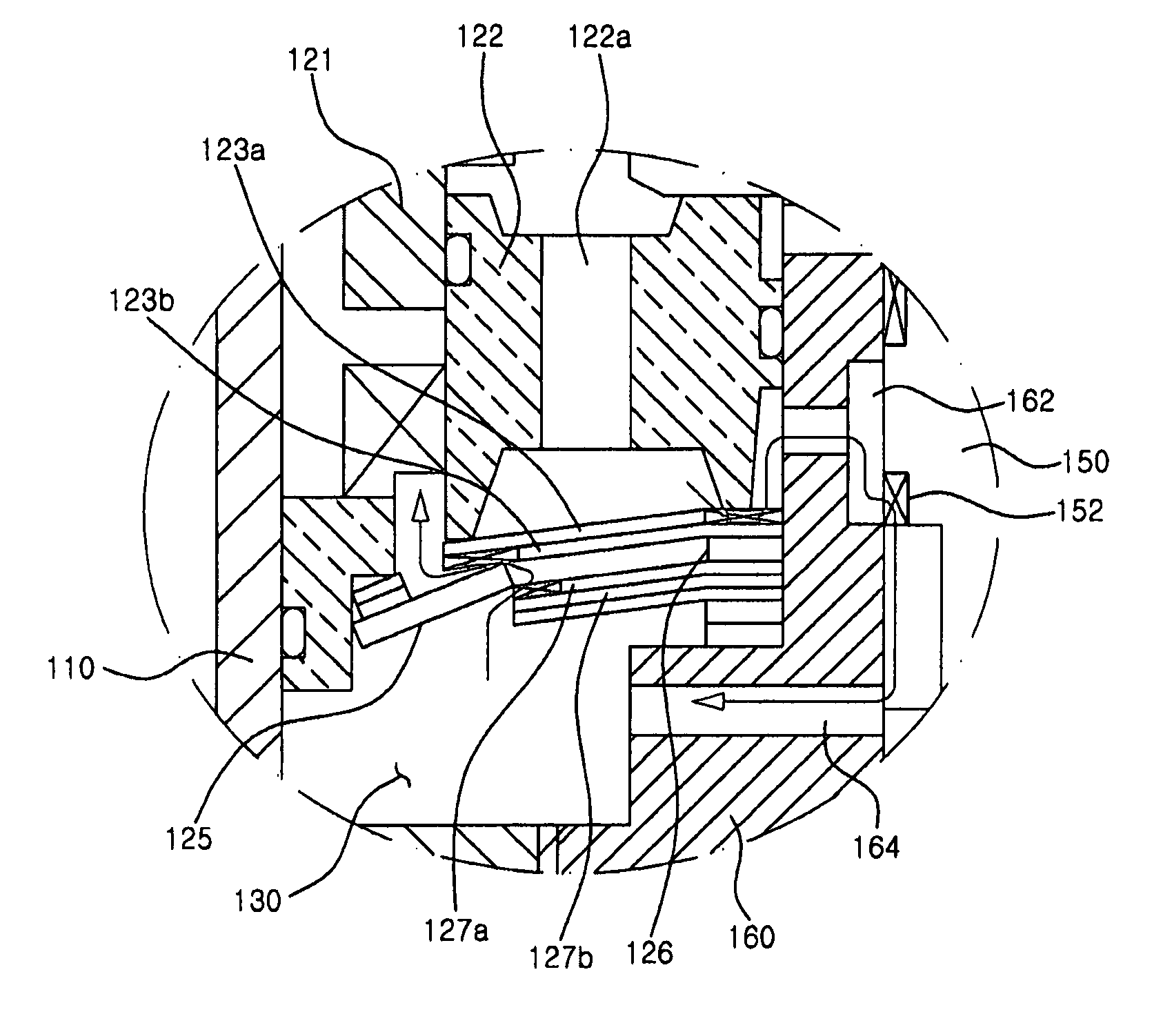
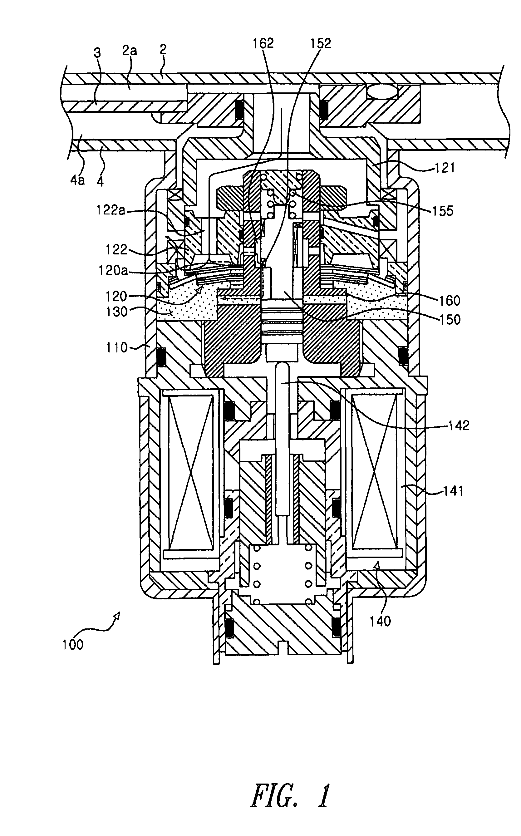
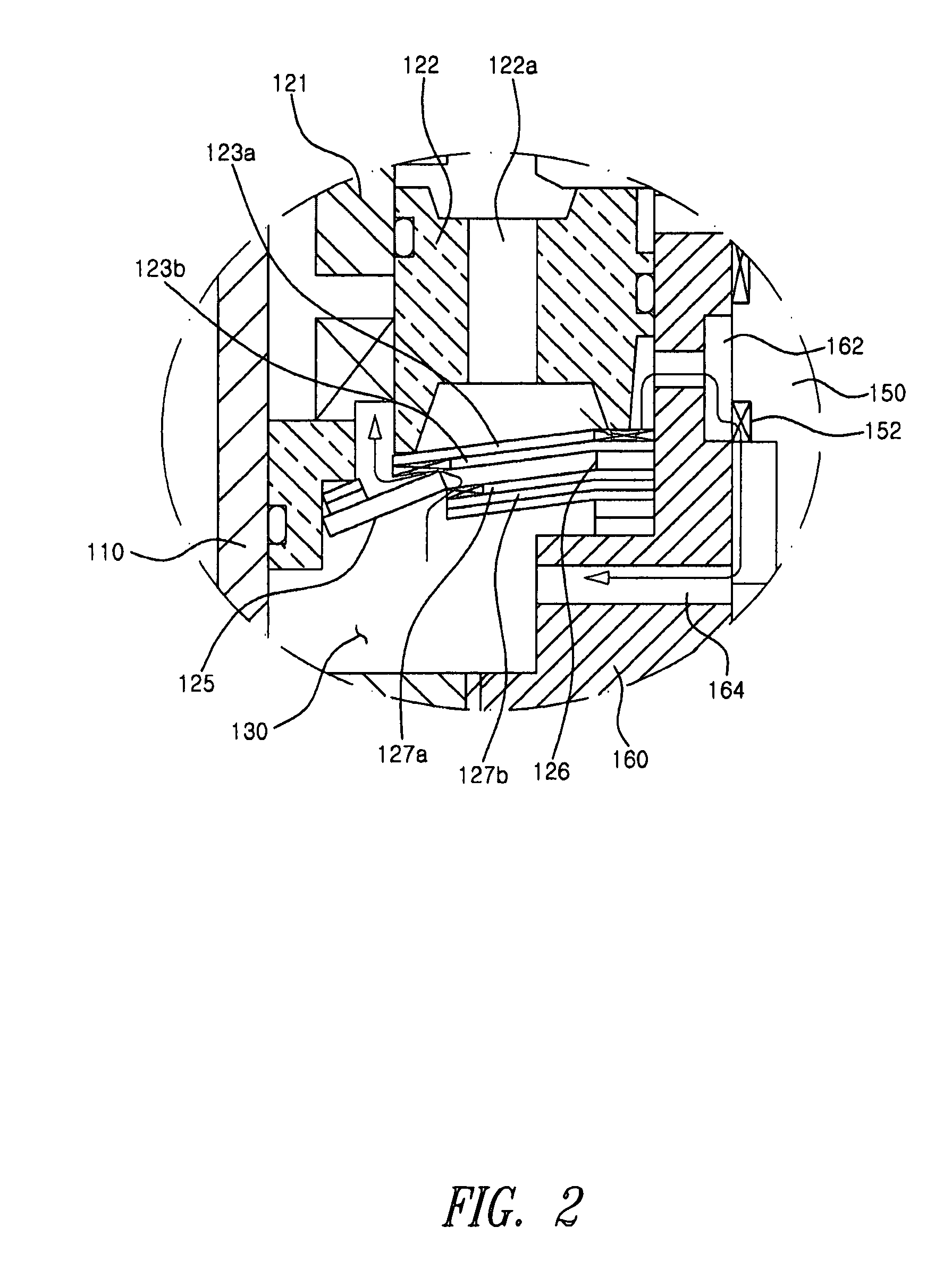
[0017]FIG. 1 is a sectional view showing a solenoid valve 100 according to an embodiment of the present invention, and FIG. 2 is an enlarged sectional view of a major portion of the solenoid valve 100.

[0018]As shown in FIGS. 1 and 2, the solenoid valve 100 according to an embodiment of the present invention is provided on an outside of a shock absorber. The shock absorber comprises an intermediate tube 3 between an internal tube 2 and an external tube 4. The shock absorber has a high pressure flow passage 2a and a low pressure flow passage 4a, which are in fluid communication with the internal tube 2 of the shock absorber through holes (not shown).

[0019]The solenoid valve 100 ...


PUM


Abstract

The present invention relates to a solenoid valve configured to be mounted to a shock absorber of a vehicle to adjust damping force. solenoid valve of a shock absorber in which a damping force is adjusted through adjustment of back pressure against a disc valve. The solenoid valve includes a back pressure chamber for generating back pressure against the disc valve by a fluid introduced through a back pressure adjusting flow passage, and a spool moved in a spool guide by operation of a solenoid to control opening / closing or opening rate of the back pressure adjusting flow passage. The back pressure adjusting flow passage includes a variable orifice with an opening rate of the variable orifice being adjusted by the spool and the spool guide, the back pressure chamber, and a fixed orifice formed on the disc valve.

Description

BACKGROUND[0001]1. Technical Field[0002]The present invention relates to a solenoid valve mounted to a shock absorber of a vehicle to adjust damping force.[0003]2. Description of the Related Art[0004]As a vehicle becomes popularized, a level of the customer's knowledge and requirement for the vehicle gets higher, and functional performances such as output power, silence, ride comfort, handling stability and the like as well as purpose, convenience and economical efficiency of the vehicle become import selection criterions of customers who will purchase a vehicle.[0005]A vehicle is continuously subjected to vibration or shock transmitted from the road through road wheels during driving of the vehicle. Thus, a shock absorbing device is provided between a vehicle body (or a frame) and an axle (or a wheel shaft) to prevent vibration or shock from being transmitted directly to the vehicle body, thereby improving ride comfort of the vehicle. In addition, driving stability of the vehicle i...

Claims


Application Information

Patent Timeline
Patent Type & Authority Patents(United States)
IPC IPC(8): F16K31/02
CPCB60G17/018F16F9/465B60G2202/24B60G2206/41B60G2500/104B60G2500/112B60G2600/26F16F9/34F16F9/50
Inventor JEE, YOUNG HWAN
Owner HL MANDO CORP
Why Eureka
Try Eureka