Panel and panel fastening system

a technology of fastening system and panel, which is applied in the direction of tongue/groove making apparatus, furniture parts, couplings, etc., can solve the problems of insufficient durability of the connection, especially in the direction of the perpendicular joining movement, and the re-engaging of the hook connection once it has come undone, so as to achieve the effect of reducing the amount of elastic deformation of the walls of the opening, reducing the amount of elastic deformation of the walls, and achieving

Inactive Publication Date: 2011-03-01
AKZENTA PANEELE PROFILE GMBH
View PDF124 Cites 152 Cited by
  • Summary
  • Abstract
  • Description
  • Claims
  • Application Information

AI Technical Summary

Benefits of technology

[0036]The hinge properties of two interconnected panels can be further improved if the wall of the opening of a panel, which is towards the base, has on its inside an inclined removal of material which extends to the free end of the wall and the wall thickness of said wall is increasingly thinner towards the free end. In that case, a free space for movement for the common hinge is provided by the removal of material, in the laid condition of two panels.
[0037]With that improvement, the amount of elastic deformability of the walls of the opening is further reduced, during flexing of the laid panels in an upward direction.
[0038]It is also desirable if the opening of a panel can be enlarged for connection to the projection of a further panel by resilient deformation of its lower wall and the resilient deformation of the lower wall, which occurs during the joining operation, is reversed again in the finished joined condition of two panels. In that way the positively engaging profiles are elastically deformed only for the joining operation and during a pivotal hinge movement and are not subjected to any elastic stressing when they are not loaded.
[0039]Preferably, the positively engaging profiles are formed integrally at the narrow sides of the panels. The panels can be produced very easily and with a low level of waste.
[0040]It has been found that the strength of mode...

Problems solved by technology

In the arrangement of EP 0 715 037 A1 that problem arises for example if a soft underlay for damping the sound of footsteps is provided between the base and the panels.
In a flat assembly comprising a very large number of individual panels, a problem, which arises, is that of re-engag...

Method used


Image

  • Panel and panel fastening system
  • Panel and panel fastening system
  • Panel and panel fastening system

Examples


Embodiment Construction

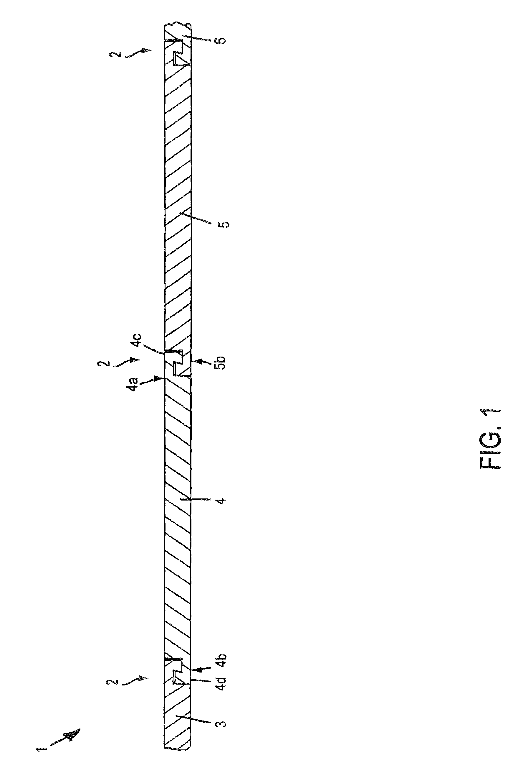
[0056]Referring to FIG. 1 of the drawing a floor covering 1 with the proposed fastening system 2 is composed of a plurality of similar panels 3, 4, 5 and 6. The first panel 4 has at mutually opposite narrow sides mutually matching retaining profiles 4a and 4b with complementary hook elements 4c and 4d. In that way, it is always possible for a first retaining profile 4a to be joined to a second retaining profile 5b of a second panel 5.

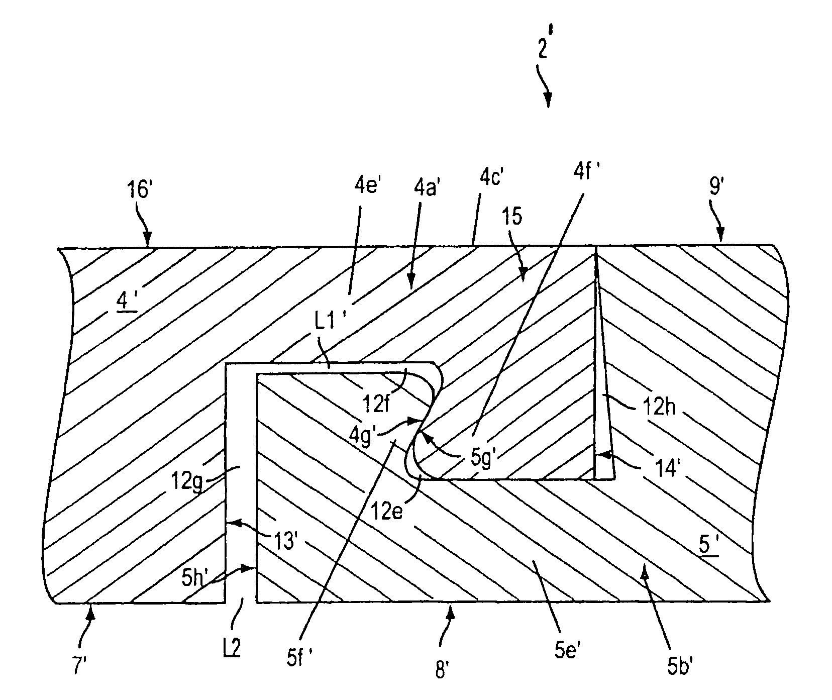
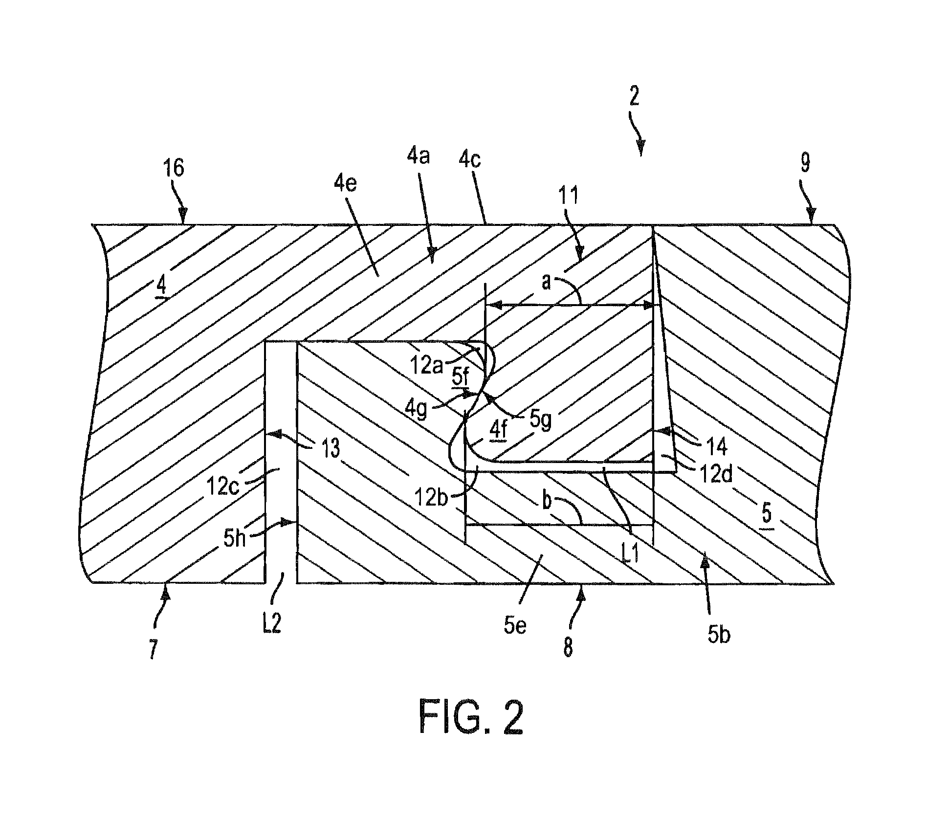
[0057]FIG. 2 shows a side view on an enlarged scale of a portion of an embodiment of the fastening system 2. FIG. 2 shows a first retaining profile 4a of a panel 4 with a hook element 4c that is formed from a leg 4e that projects substantially perpendicularly from the narrow side and is arranged at the top side 16 of the panel 4. In this case, a hook projection 4f that faces towards the underside 7 of the panel 4 is arranged at the free end of the leg 4e. The hook projection 4f is in engagement with a hook projection 5f of a second panel 5. The hook pro...


PUM

PropertyMeasurementUnit
Adhesivityaaaaaaaaaa
Deformation enthalpyaaaaaaaaaa

Abstract

A panel fastening system, especially for floor panels. The floor panels are fitted with retaining profiles on their edges, whereby the retaining profile of a front edge and the retaining profile of the opposite back edge and the retaining profile of a left edge and the retaining profile of the opposite right edge of a panel match each other in such a way that similar panels can be fixed to one another. The mutually matching retaining profiles have complementary hook elements that can be hooked into one another and the hook elements have retaining surfaces by means of which the panels are held against each other when mounted in such a way that a gap-free surface is obtained.

Description

BACKGROUND OF THE INVENTION[0001]The invention relates to a fastening system for panels, with retaining profiles arranged at the narrow sides of the panels, in particular for floor panels, wherein mutually opposite retaining profiles of a panel match each other in such a way that similar panels can be fastened to one another, wherein at least one pair of oppositely disposed retaining profiles has complementary hook elements that can be hooked one into the other and that the hook elements have hook projections with retaining surfaces by which the panels, in the assembled condition, are held against each other in such a way that there is a gap-free floor surface.[0002]A fastening system of the general kind set forth is known from EP 0 715 037 A1. FIGS. 1 and 2 of that publication propose a fastening system whose hook elements can be fitted one into the other by a joining movement perpendicular to the panel laying plane. As can be very clearly seen from FIG. 1 of that publication the c...

Claims


Application Information

Patent Timeline
IPC IPC(8): A47B96/06E04B2/00B27F1/04E04F15/04
CPCB27F1/04E04F15/02E04F15/04E04F2201/0115E04F2201/0138Y10T403/655E04F2201/0153E04F2201/023E04F2201/025E04F2201/07Y10T403/65E04F2201/0146
Inventor HANNIG, HANS-JURGENEISERMANN, RALF
Owner AKZENTA PANEELE PROFILE GMBH
Why Eureka
Try Eureka