Eureka AIR delivers breakthrough ideas for toughest innovation challenges, trusted by R&D personnel around the world.

Fuel cell vehicle including reaction-off gas discharge system

a fuel cell and gas discharge technology, applied in battery/fuel cell control arrangement, electrochemical generators, electric propulsion mounting, etc., can solve the problems of fuel cell vehicle freezing inside the humidifying device, reducing the air flow rate into the dilution device, and unable to start, so as to achieve the effect of stably introducing air and improving the dilution performance of the dilution devi

Inactive Publication Date: 2011-03-01
TOYOTA JIDOSHA KK
View PDF39 Cites 0 Cited by
  • Summary
  • Abstract
  • Description
  • Claims
  • Application Information

AI Technical Summary

Benefits of technology

[0009]It is therefore an object of the present invention to solve the problems as described above, and to prevent reverse flow of water from the pipe in the downstream side from the humidifying device to the humidifying device and improve the dilution performance of the dilution device.
[0013]The reaction off-gas discharged from the humidifying device is separated to gas and liquid by a centrifugal force in the course of being delivered in the bent discharge flow passage, and therefore, the dilution device can stably introduce air. The dilution performance of the dilution device can be thereby improved.

Problems solved by technology

However, when an outlet, from which the oxidizing off-gas from the humidifying device is discharged, opens toward the back side of a fuel cell vehicle which discharges the oxidizing off-gas toward its back side, the following problems occur.
For example, when the fuel cell vehicle is stopped with its front side downwardly inclined in an environment below the freezing point, there is a possibility that water remaining in a pipe in the downstream side from the humidifying device flows back to the humidifying device and freezes inside the humidifying device.
When water freezes inside the humidifying device, a reaction gas flow passage is closed and the fuel cell vehicle cannot be started.
However, when the humidifying device and a dilution device are connected by a straight pipe, there is a possibility that an air flow rate into the dilution device decreases and its dilution performance is deteriorated since produced water by a cell reaction, water vapor or the like is mixed in the oxidizing off-gas flowing from the humidifying device to the dilution device in such a state that the produced water or the water vapor is not separated from air.

Method used


Image

  • Fuel cell vehicle including reaction-off gas discharge system
  • Fuel cell vehicle including reaction-off gas discharge system
  • Fuel cell vehicle including reaction-off gas discharge system

Examples


Embodiment Construction

[0017]The embodiment of the present invention will be described below with reference to each drawing.

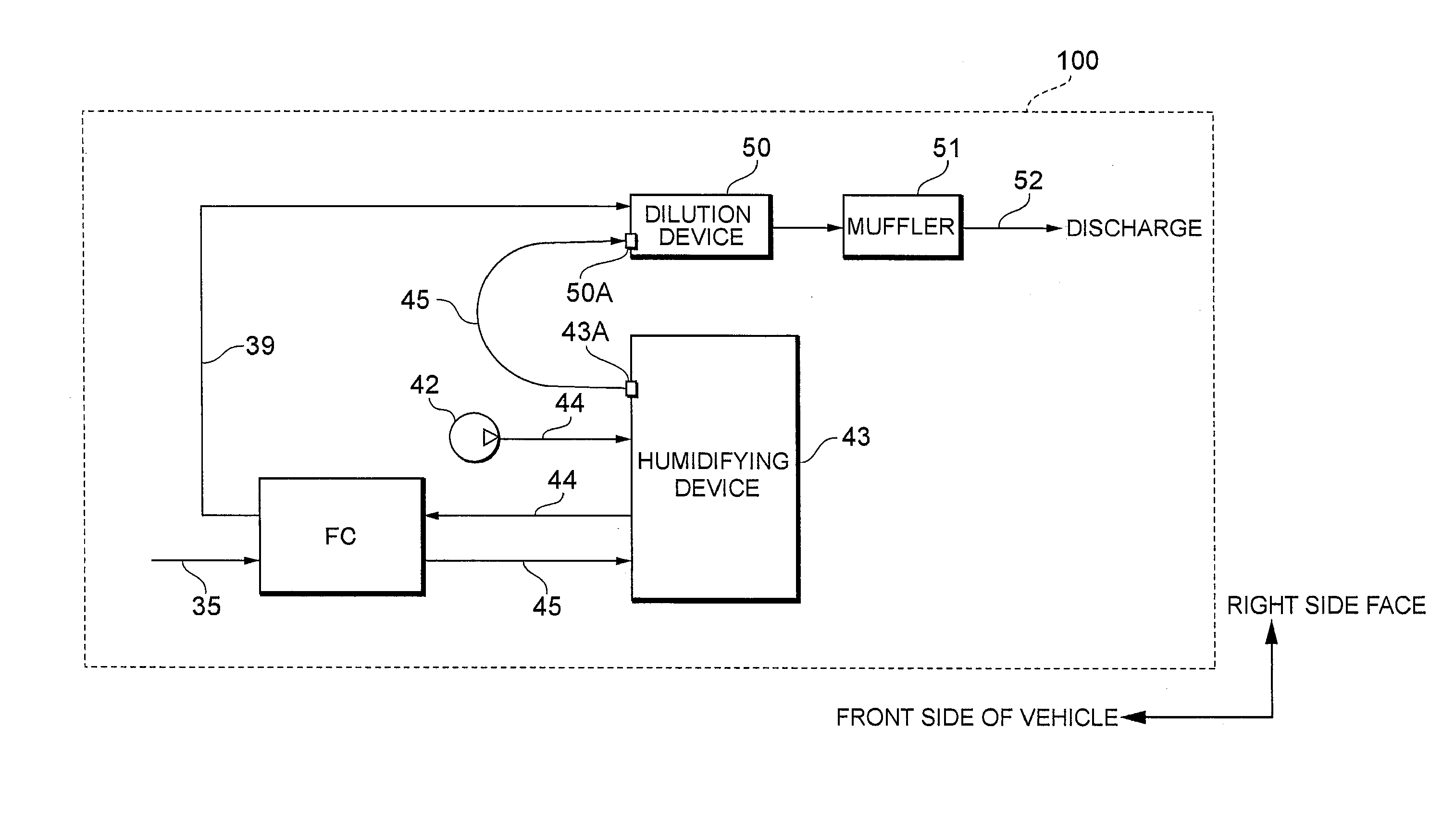
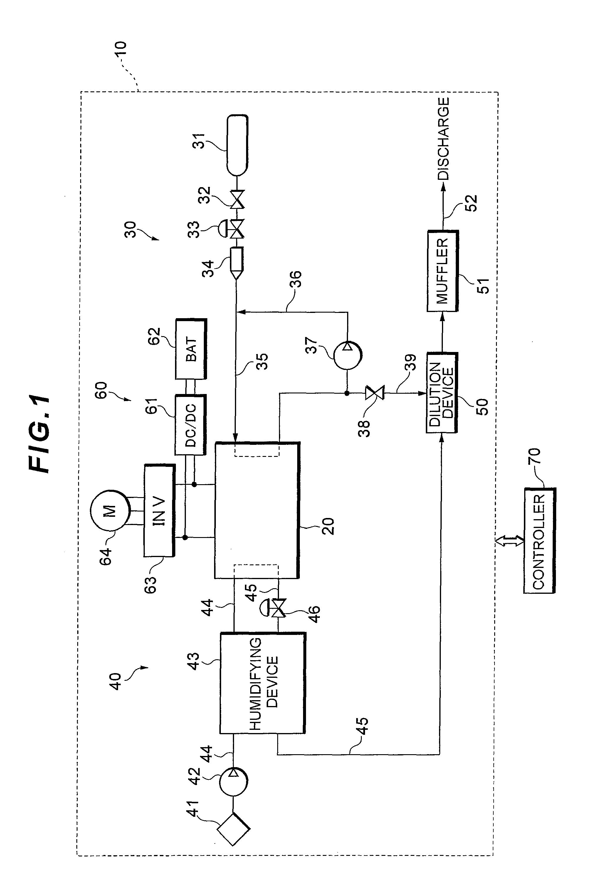
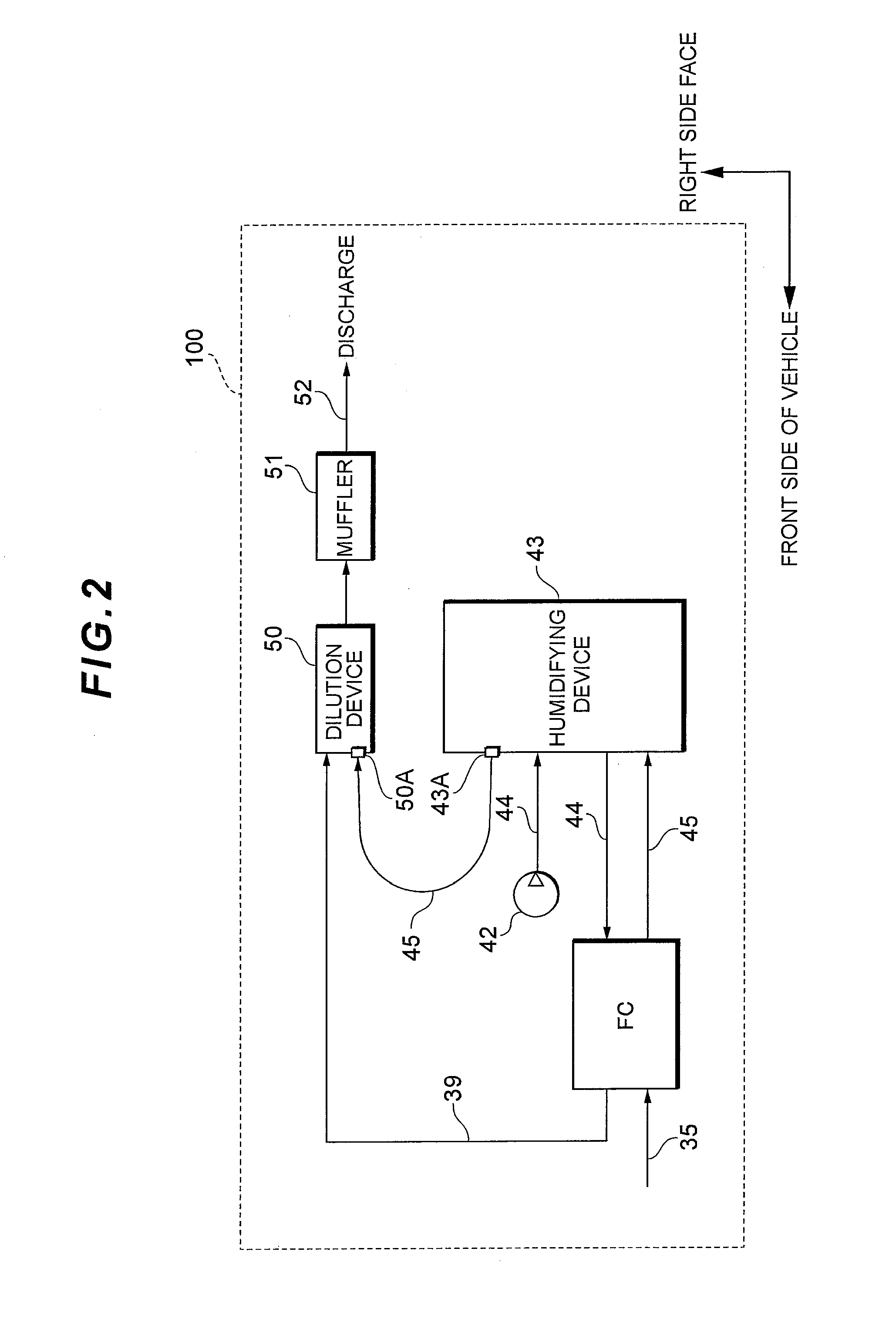
[0018]FIG. 1 shows a system configuration of a fuel cell system 10 which serves as an in-vehicle power source system of a fuel cell vehicle.

[0019]The fuel cell system 10 comprises a fuel cell stack 20 for generating electric power by receiving supply of a reaction gas (oxidizing gas and fuel gas), a fuel gas piping system 30 for supplying a hydrogen gas as the fuel gas to the fuel cell stack 20, an oxidizing gas piping system 40 for supplying air as the oxidizing gas to the fuel cell stack 20, an electric power system 60 for controlling charge and discharge of electric power, and a controller 70 for generally controlling the entire system.

[0020]The fuel cell stack 20 is, for example, a solid polymer electrolyte cell stack constituted by a plurality of cells serially stacked in layers. The cells comprise a cathode disposed on one side of an electrolyte membrane constituted by an ion-e...


PUM

PropertyMeasurementUnit
pressureaaaaaaaaaa
pressureaaaaaaaaaa
pressureaaaaaaaaaa

Abstract

A fuel cell vehicle includes: a fuel cell stack for generating electric power by receiving supply of a reaction gas; a humidifying device for delivering an oxidizing off-gas discharged from the fuel cell stack and an oxidizing gas with a water vapor permeable membrane interposed therebetween, and thereby carrying out a moisture exchange between the oxidizing off-gas and the oxidizing gas; and a discharge flow passage for discharging the oxidizing off-gas discharged from the humidifying device to an outside of the vehicle. An oxidizing off-gas outlet that opens toward a front side of the vehicle is formed in the humidifying device. The discharge flow passage is connected to the oxidizing off-gas outlet and is bent in an approximate U shape from a front side of the vehicle to a back side of the vehicle.

Description

[0001]This is a 371 national phase application of PCT / JP2007 / 069398 filed 27 Sep. 2007, which claims priority to Japanese Patent Application No. 2006-291729 filed 26 Oct. 2006, the contents of which are incorporated herein by reference.TECHNICAL FIELD[0002]The present invention relates to a fuel cell vehicle in which a fuel cell system is mounted.BACKGROUND ART[0003]Fuel cell systems are energy conversion systems for supplying a fuel gas and an oxidizing gas to a membrane electrode assembly and generating an electrochemical reaction, so as to convert chemical energy to electrical energy. Among the fuel cell systems, a solid polymer electrolyte fuel cell stack in which a solid polymer membrane is used as an electrolyte is expected to be used as an in-vehicle power source system since the solid polymer electrolyte fuel cell stack can be miniaturized at low cost and has a high output density.[0004]In the fuel cell stack, hydrogen ion produced in an anode moves through an electrolyte me...

Claims


Application Information

Patent Timeline
Patent Type & Authority Patents(United States)
IPC IPC(8): H01M8/04
CPCB60L11/1881B60L11/1892H01M8/04141H01M8/04149Y02E60/50H01M2250/20Y02T90/32Y02T90/34B60L58/30B60L58/33Y02T90/40
Inventor TAKESHITA, MASAHIROINOUE, SHIGEYUKI
Owner TOYOTA JIDOSHA KK
Why Eureka
Eureka Blog
Learn More