Method and apparatus for detecting defects on a disk surface
a technology of a disk surface and a detection method, which is applied in the direction of instruments, digital computer details, transmission, etc., can solve the problems of affecting the accuracy of magnetic reading and writing operations, unstable floating amount of a head, and deterioration of the character of a product, so as to accurately distinguish and detect defects
- Summary
- Abstract
- Description
- Claims
- Application Information
AI Technical Summary
Benefits of technology
Problems solved by technology
Method used
Image

Examples
first embodiment
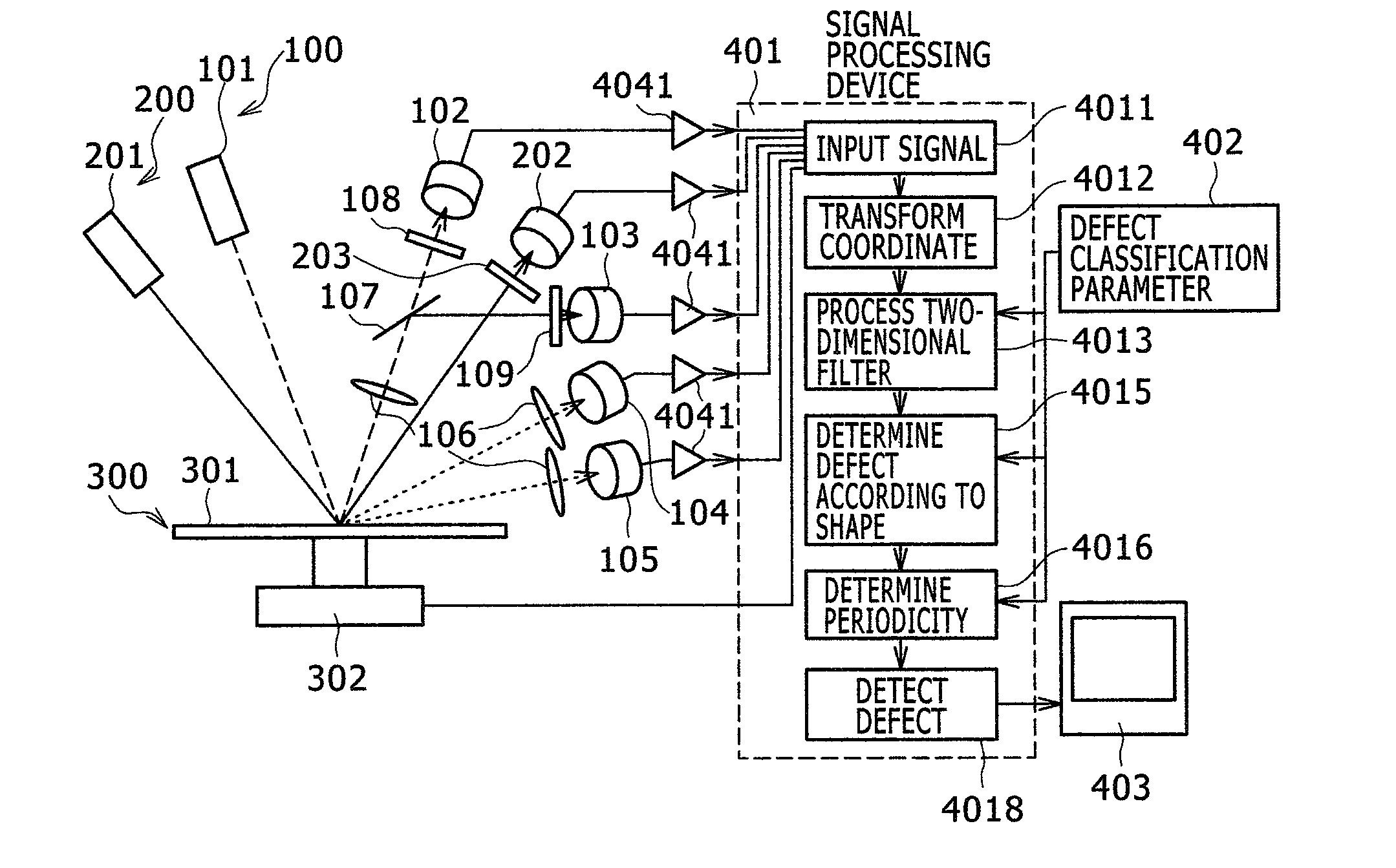
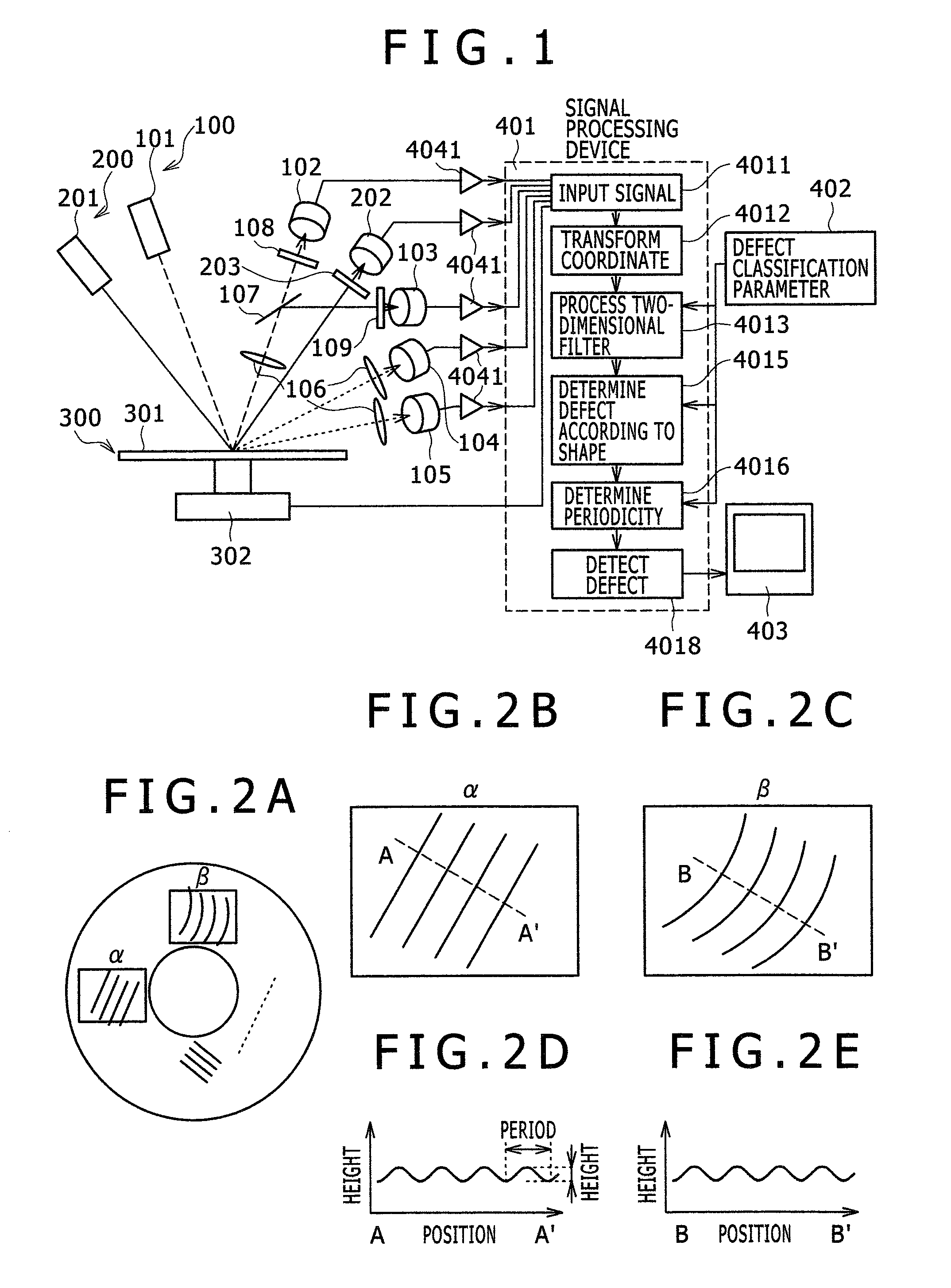
[0068]FIG. 1 is a diagram schematically showing an entire configuration of an apparatus for detecting defects on a disk surface according to a first embodiment. As shown in FIG. 1, the apparatus for detecting defects on a disk surface includes dual optical systems 100 and 200 that are each configured with a light transmitting system and a light receiving system. For example, the first optical system 100 detects pit, handling damage, stain, particle, and scratch defects and the second optical system 200 detects bump, dimple, and glide defects. In other words, the plural optical systems are disposed according to the kind of defect. The first light transmitting system 101 projects light to form laser spots on a surface of a disk 301, and the second light transmitting system 201 projects parallel light having a predetermined width, which can detect defects, on the surface of the disk 301 and at the same time, scans the position thereof on the surface of the disk 301 in a spiral shape at...
second embodiment
[0096]Next, the determination method of the wrinkle defect generated in the circular arc shape will be described as the second embodiment. FIG. 14 describes an image processing flow on the defect having the features of the circular arc distribution. The processing contents from 4011 to 4013 of FIG. 14 are the same as the process described in FIG. 7.
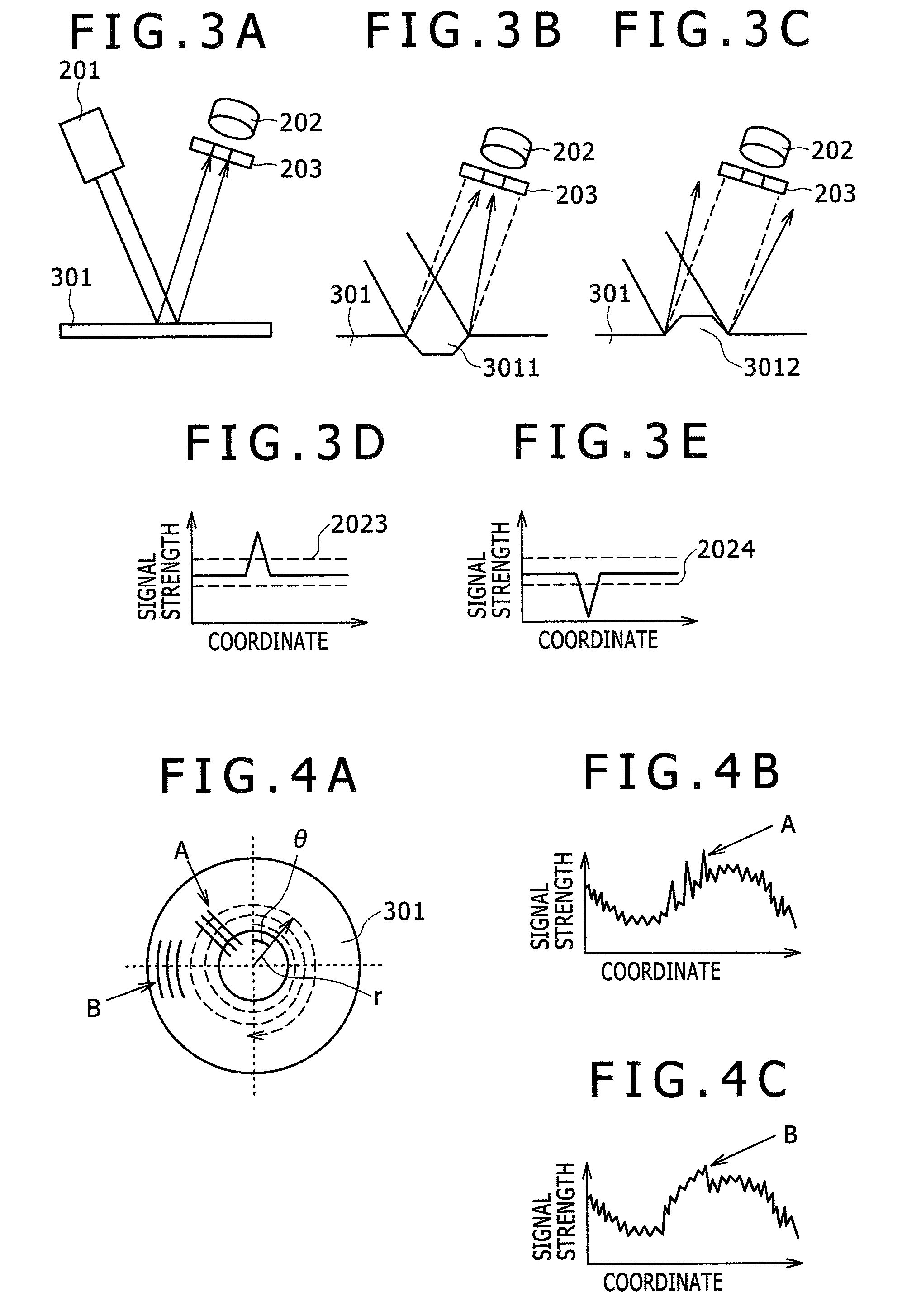
[0097]Next, the extraction of circular arc component of the image binarized by the process is performed (40141). As an example for performing the circular arc detection, the Hough transform method is used. FIGS. 15A and 15B show a principle of the Hough transformation. For example, in FIG. 15A, if three points, that is, P1, P2, and P3 exist on the same circle having a radius r, the circle equation becomes the following equation.
(x−a)2+(y−b)2=r2 [Equation 8]
[0098]However, a and b become the center coordinate of a circle. The method for obtaining the center coordinate (a and b) indicates the circle having the radius r based on the points P...
third embodiment
[0113]Although the first embodiment relates to the detection of the periodicity linear defect and the second embodiment relates to the detection of the periodicity circular arc defect, it is preferable to simultaneously perform detection of these defects in the same apparatus. In this case, in the flow chart of FIG. 7, it is preferable that after the straight line detection step (4014) and the linear defect determination step (4015) or simultaneously with the above steps, the circular arc detection step (40141) and the circular arc defect determination step (40161) shown in FIG. 14 are performed. Thereby, it is possible to detect the periodicity linear defect and the periodicity circular arc defect, which are the wrinkle defect of the disk.
PUM
| Property | Measurement | Unit |
|---|---|---|
| frequency | aaaaa | aaaaa |
| length | aaaaa | aaaaa |
| height | aaaaa | aaaaa |
Abstract
Description
Claims
Application Information
 - R&D
- Intellectual Property
- Life Sciences
- Materials
- Tech Scout
- Unparalleled Data Quality
- Higher Quality Content
- 60% Fewer Hallucinations
Browse by: Latest US Patents, China's latest patents, Technical Efficacy Thesaurus, Application Domain, Technology Topic, Popular Technical Reports.
© 2025 PatSnap. All rights reserved.Legal|Privacy policy|Modern Slavery Act Transparency Statement|Sitemap|About US| Contact US: help@patsnap.com