
Floor tile with load bearing lattice

a technology of floor tiles and lattices, which is applied in the direction of flooring, walls, treads, etc., can solve the problems of not being well suited not being well suited for active or sports play, and most conventional flooring materials are not well suited for all of these various types of us

Inactive Publication Date: 2011-03-08
CONNOR SPORT COURT INT
View PDF161 Cites 96 Cited by
  • Summary
  • Abstract
  • Description
  • Claims
  • Application Information

AI Technical Summary

Benefits of technology

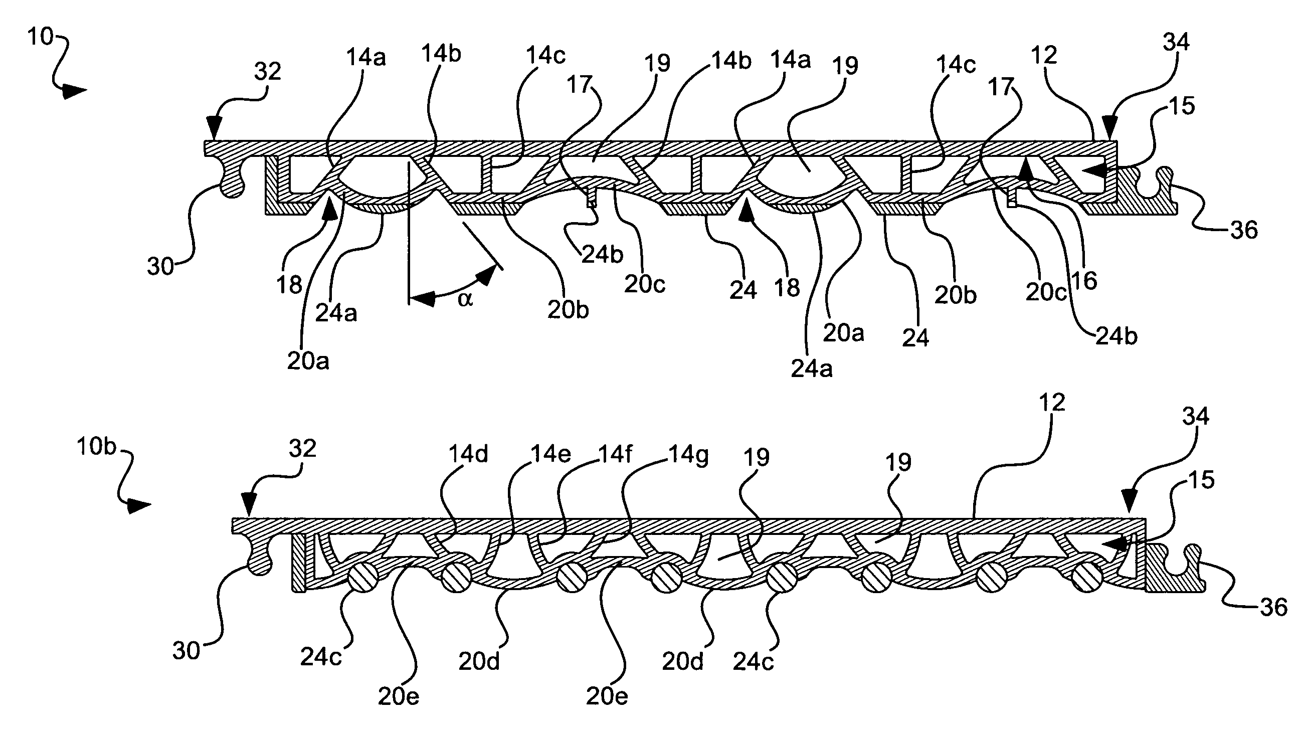
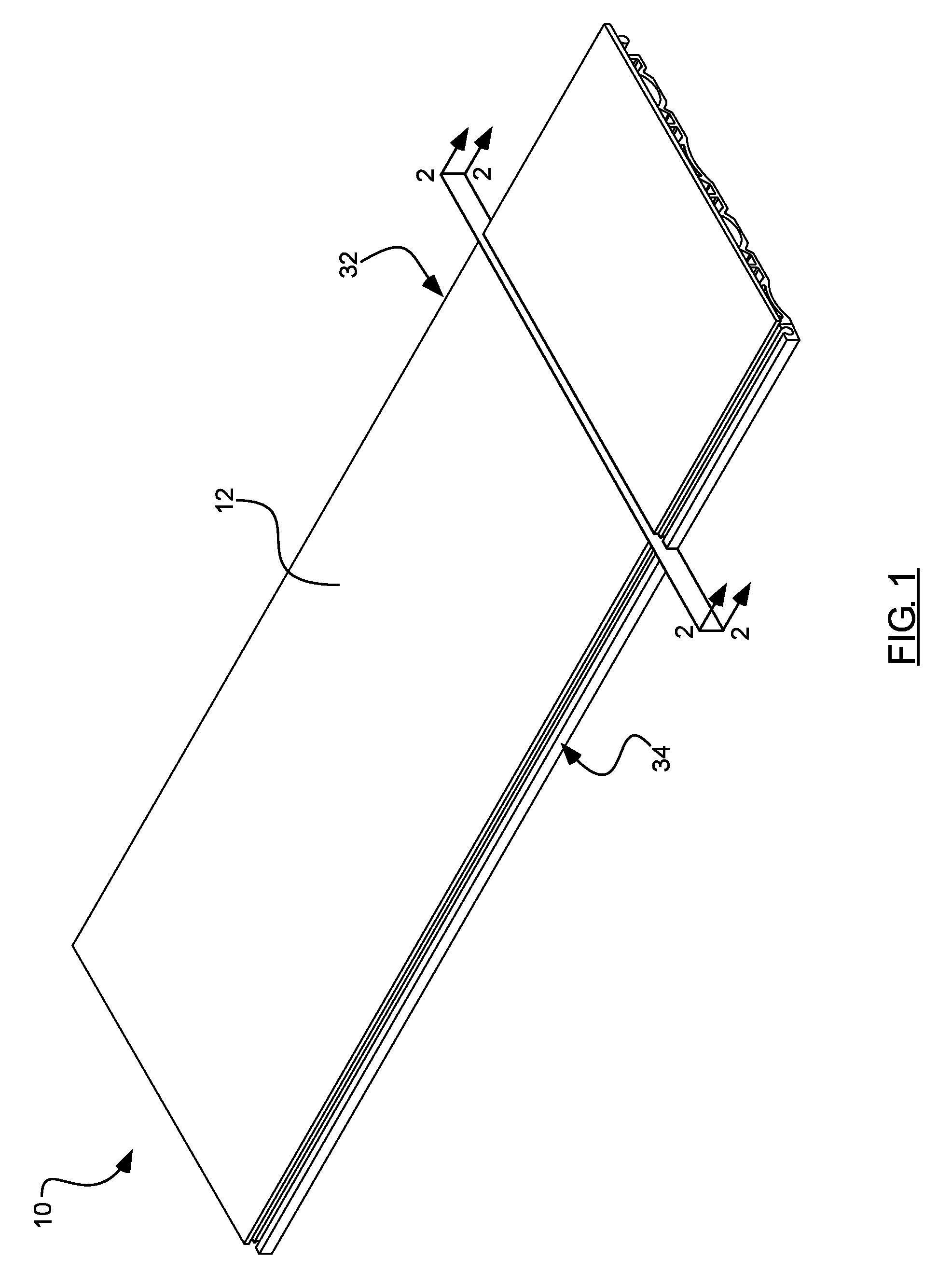
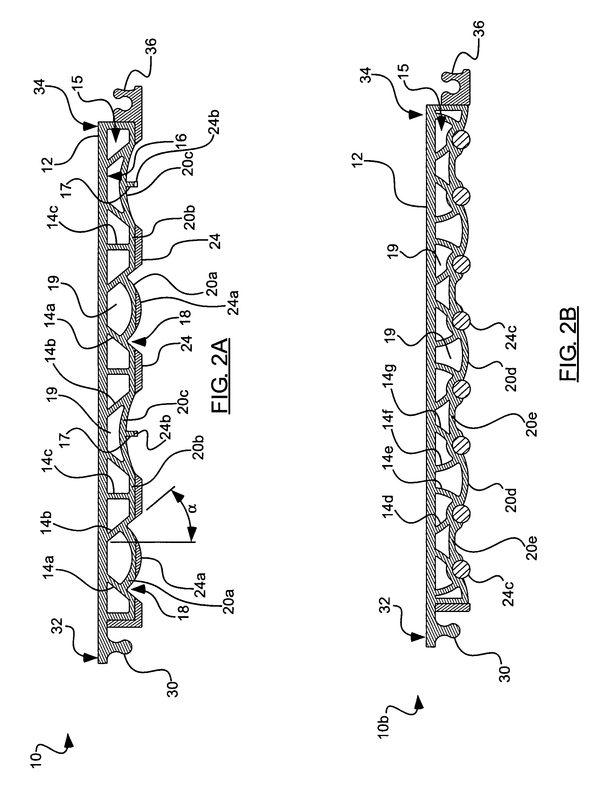
[0008]The present invention provides a floor tile for use in a flooring system, including an upper surface operable for use as a portion of a flooring installation and a support lattice operable to support the upper surface. The support lattice can include a plurality of support members extending downwardly from an underside of the upper surface and terminating in lower sections collectively defining a subfloor contact profile. A plurality of interconnecting members can laterally interconnect two or more of the support members. At least some of the plurality of support members can extend downwardly at an oblique angle to the upper surface.
[0009]In accordance with another aspect of the invention, a floor tile for use in a flooring system is provided, including an upper surface operable for use as a portion of a flooring installation and a support lattice configured to support the upper surface. The support lattice can include a plurality of rails extending longitudinally along an underside of the upper surface and defining a plurality of open spaces therebetween. Each of the plurality of rails can extend downwardly and can terminate in a lower section, with the lower sections collectively defining a subfloor con

Problems solved by technology

While the cafeteria floor in this example would be considered a “multi-purpose” floor, most conventional flooring materials are not well-suited for all of these various types of use.
It has been found that flooring materials best suited for long wear, ease of cleaning and maintenance and ease of installation, for example, have often been not well suited for active or sports play.
However, most so-called multipurpose floors are generally very hard and do not provide an adequate level of resiliency.
In a similar fashion, most conventional flooring products that provide good resiliency do not also meet the other requirements of a multipurpose floor: e.g., they may be expensive to install and maintain, and may not withstand the heavy loads periodically applied to multipurpose floors.
In particular, conventional flooring products that provide good resiliency perform very poorly under “rolling load” conditions (e.g., conditions in which a heavy load is rolled across the floor, as in the case, for example, where a piano is moved across a floor).
Despite these attributes, however, VCT has several drawbacks when used as part of a floor that is to be subject to general-purpose use, and is particularly unsuited for active play or sports use.
Perhaps the biggest drawback of VCT is that it is very unforgiving, e.g., it is very much nonresilient.
Because of its high limestone content, VCT provides little or no cushioning or shock absorbency, and thus increases the likelihood of injuries occurring during falls, as well as the risk of tendonitis, stress fractures, and joint damage over an extended period of time from playing sports or participating in active play on the VCT floor.
This presents a significant problem, especially in school gymnasiums where children are continually participating in active play.
Playing daily on a VCT floor can cause both short and long-term injuries to children.
For example, without proper protection, a fall from as little as 2 feet, or a direct fall from only 1½ inches, can result in a skull fracture or other traumatic brain injury, as well as broken or fractured bones.
Moreover, VCT can be extremely slippery as it does not provide a great amount of surface friction, thus increasing the likelihood of slips and falls.

Method used


Image

  • Floor tile with load bearing lattice
  • Floor tile with load bearing lattice
  • Floor tile with load bearing lattice

Examples


Embodiment Construction

[0018]Before the present invention is disclosed and described, it is to be understood that this invention is not limited to the particular structures, process steps, or materials disclosed herein, but is extended to equivalents thereof as would be recognized by those of ordinary skill in the relevant arts. It should also be understood that terminology employed herein is used for the purpose of describing particular embodiments only and is not intended to be limiting.

[0019]It must be noted that, as used in this specification and the appended claims, the singular forms “a” and “the” include plural referents, unless the context clearly dictates otherwise. Thus, for example, reference to a “support member” includes one or more of such support members, unless the context clearly dictates otherwise.

DEFINITIONS

[0020]In describing and claiming the present invention, the following terminology will be used in accordance with the definitions set forth below.

[0021]As used herein, relative terms...


PUM

PropertyMeasurementUnit
Angleaaaaaaaaaa
Lengthaaaaaaaaaa
Angleaaaaaaaaaa

Abstract

A floor tile for use in a flooring system comprises an upper surface operable for use as a portion of a flooring installation and a support lattice operable to support the upper surface. The support lattice includes a plurality of support members extending downwardly from an underside of the upper surface and terminating in lower sections collectively defining a subfloor contact profile and a plurality of interconnecting members laterally interconnecting two or more of the support members. At least some of the plurality of support members extend downwardly at an oblique angle to the upper surface.

Description

[0001]Priority is claimed to U.S. Provisional Patent Application Ser. No. 60 / 787,010, filed Mar. 28, 2006, which is hereby incorporated herein by reference in its entirety.FIELD OF THE INVENTIONBackground[0002]The present invention relates generally to modular floor tiles for use in flooring installations. More specifically, the present invention relates to modular floor tiles having load bearing lattices associated therewith.RELATED ART[0003]It is often desired that a flooring installation be suitable for use in a variety of activities. Such flooring installations are often referred to as “multi-purpose” floors. For example, the floor in a typical primary school cafeteria is used to support tables and chairs to allow children to eat, and should be able to withstand repeated movement of tables, chairs and related equipment onto and off of the flooring surface. This same floor is also often used at other times for performance purposes, such as when students present musical or dramati...

Claims


Application Information

Patent Timeline
IPC IPC(8): E04F15/00
CPCE04F15/10E04F2201/0138E04F2203/04E04F15/082E04F15/087
Inventor YOKUBISON, RONALDMOHR, TROY D.HANEY, THAYNESMITH, DAVID F.
Owner CONNOR SPORT COURT INT
Learn More