Low power consumption lock for appliance latch

a low-power consumption, latch technology, applied in the direction of mechanical equipment, carpet fasteners, cleaning equipment, etc., can solve the problems of inability to provide rapid locking and unlocking, increase the size and expense of the coil winding, and lock movement without electrical power application, etc., to achieve low actuation thresholds, reliable operation, and efficient operation

Active Publication Date: 2011-03-08
ILLINOIS TOOL WORKS INC
View PDF24 Cites 11 Cited by
  • Summary
  • Abstract
  • Description
  • Claims
  • Application Information

AI Technical Summary

Benefits of technology

Thus, it is a feature of at least one embodiment of the invention to provide a mechanism that distinguishes between forces caused by electrical actuation and forces caused by shocks, and to allow movement only in the absence of forces caused by shocks. It is another feature of at least one embodiment of the invention to provide a system that allows the bi-stable actuator to have low actuation thresholds for efficient operation and reliable operation.
It is thus a feature of at least one embodiment of the invention to provide a simple mechanical system for detecting acceleration and producing an actuation force.
Thus, it is a feature of at least one embodiment of the invention to provide a mechanical system that may be easily tailored to a variety of applications.
Thus, it is a feature of at least one embodiment of the invention to provide a mechanism that distinguishes between forces cause by electrical actuation and forces caused by shocks, and to allow movement only in the presence of forces caused by electrical actuation. It is again a feature of at least one embodiment of the invention to provide a system that allows the bi-stable actuator to have low actuation thresholds for efficient operation and reliable operation.
Thus, it is a feature of at least one embodiment of the invention to provide a simple electrically actuated mechanism preventing inadvertent movement of the lock.
Thus, it is a feature of at least one embodiment of the invention to provide a simple mechanism that takes advantage of the solenoid already used as the bi-stable actuator.

Problems solved by technology

In the case of a solenoid, this continuous duty requires increased size and expense of the coil windings which must be rated for continuous duty.
A disadvantage of wax motors and bimetallic strips is that they rely on a heating process and thus cannot provide rapid locking and unlocking.
During shipment of an appliance with a bi-stable lock, transportation shocks may cause the lock to move without the application of electrical power, for example, from the unlocked position to the locked position.
This unintended locking of the appliance door can be inconvenient for the end user who may need access to the interior of the appliance before the appliance is installed and connected to electrical power, for example, to obtain parts or appliance manuals from the interior of the appliance.
This approach, however, necessitates a larger electromagnetic actuator, defeating to some extent the motivation for using a bi-stable actuator.
Frictional elements can be difficult to manufacture so that they provide a consistent friction over the life of the product.

Method used


Image

  • Low power consumption lock for appliance latch
  • Low power consumption lock for appliance latch
  • Low power consumption lock for appliance latch

Examples


first embodiment

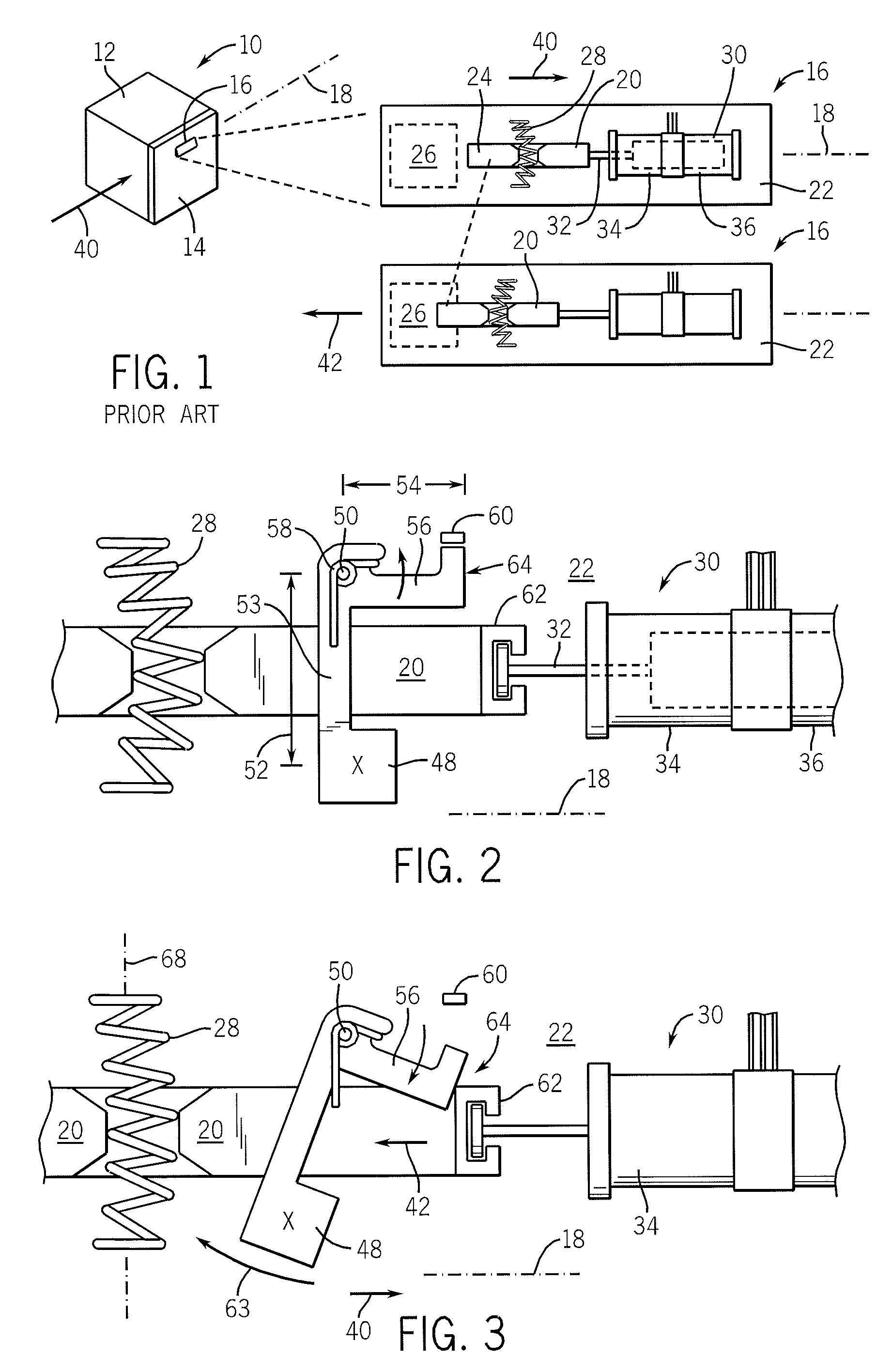
Referring now to FIG. 2, the slide 20 may rest in an unlocked state before application of any accelerative forces. In the invention, a weight 48 is positioned near the slide 20 and held by an arm 53 pivoted about a pivot point 50 so that the weight 48 may move generally in a swinging radius 52 along axis 18. A lever 56 is attached to the arm 53 joining the weight 48 to the pivot point 50 at a radius 54, and, in the rest state, extending along axis 18 adjacent to the slide 20. A torsion spring 58 biases the lever 56 in a counterclockwise direction (as shown) so that one end of the lever 56 abuts a stop 60 on a lock housing preventing further motion of the lever 56 in the counterclockwise direction. The end of the lever 56 provides a blocking surface 64 adjacent to an attachment tower 62 extending upward from the slide 20 to receive one end of the core 32 of the solenoid 30.

Referring now to FIG. 3, an acceleration 40 on the housing may apply an acceleration force on the weight 48 caus...

third embodiment

Referring now to FIG. 7, in a third embodiment, the effective accelerative force 42 on slide 20 may be counteracted through the use of a compensator weight 90 pivoting about a pivot point 92 adjacent to the slide 20 so that the compensator weight 90 may rotate generally along axis 18. Compensator weight 90 connects to the pivot point 92 by means of a short lever arm 94 and then continues past the pivot point 92 in a second lever arm 96 to a point over the center of the slide 20. There, the end of the second lever arm 96 engages an upstanding peg 98 attached to the slide 20. The engagement of the second lever arm 96 and the peg 98 is by means of a slotted fork connection 100 allowing relative lateral movement between the two.

During a shock causing accelerative force 42 on the slide 20, a corresponding accelerative force 42′ will act on the compensator weight 90 biasing the compensator weight 90 in a clockwise direction about pivot point 92. This, in turn, causes the fork connection 1...


PUM


Abstract

A transportation-robust bi-stable latch mechanism preserves low actuation forces by means of an auxiliary mechanism blocking the effects of shock forces during transportation.

Description

CROSS-REFERENCE TO RELATED APPLICATIONS--STATEMENT REGARDING FEDERALLY SPONSORED RESEARCH OR DEVELOPMENT--BACKGROUND OF THE INVENTIONThe present invention relates to latching mechanisms for the door of a household appliance such as clothes washing machine, and, in particular, to an electrically actuated lock for such a latch.Appliances such as clothes washing machines and dishwashers may operate automatically through one or more cycles under the control of an automatic timer. During cycles when the consumer might be exposed to spraying water or hazardous moving parts, the door to the appliance may be locked by an electrical signal from the timer. The locking mechanism may, for example, insert a blocking member into a portion of the door latch to prevent it from being disengaged through the normal operation of the latch or may insert a blocking member directly into the door.The locking mechanism may be actuated by an electrical solenoid having an element that moves through a conducti...

Claims


Application Information

Patent Timeline
Patent Type & Authority Patents(United States)
IPC IPC(8): E05C1/02D06F34/20
CPCA47L15/4259D06F37/42E05B15/0093E05B47/0002E05B47/026E05B47/0607E05B17/2019E05B17/2034E05B17/2053E05B47/0004E05B47/0006E05B2015/0493E05B2047/0079E05B2047/0093Y10S292/69Y10T292/096Y10T292/1021Y10T292/11D06F34/20
Inventor BRAGG, JOEL C.HAPKE, KENYON A.HINTZ, MICHAEL K.MCDONALD, RANDY S.OSVATIC, MICHAEL S.SULIK, JAROD M.
Owner ILLINOIS TOOL WORKS INC
Why Eureka
Try Eureka