
Fiberoptic otoscope system

a fiberoptic and otoscope technology, applied in the field of medical instruments, can solve the problems of color change, impaired medical diagnosis, etc., and achieve the effect of reducing the possibility of violating the comfort zone of patients and being easy to adapt to

Inactive Publication Date: 2011-03-08
MEDICAL INNOVATIONS
View PDF15 Cites 12 Cited by
  • Summary
  • Abstract
  • Description
  • Claims
  • Application Information

AI Technical Summary

Benefits of technology

[0012]An adjustable “ear stop” slides over the distal end and functions as a contact point for the fingers as well as a safety stop that prevents contact with the tympanic membrane. Other features that have been incorporated in the ear stop, such as an attachment for removal of ear wax with an ear loop and a channel that allows for attachment of an alligator for retrieval of foreign bodies from the nose or ear. The present fiberoptic otoscope system can directly illuminate and image the tympanum with a greatly reduced possibility of violating a patient's comfort zone. Also, the present fiberoptic otoscope can be easily adapted to remove material or foreign objects from the auditory canal using a variety of ancillary attachments. Additionally, the present otoscope is passive, in that it contains no para-magnetic materials and generates no electric fields. Further, the present fiberoptic otoscope device is adaptable to directly interfaced with existing light sources via either a direct attachment (e.g., see U.S. Pat. No. 5,177,424), via a remote attachment, or via an ambient light collecting device.

Problems solved by technology

Without this correction color could be altered and medical diagnosis impaired.

Method used


Image

  • Fiberoptic otoscope system
  • Fiberoptic otoscope system
  • Fiberoptic otoscope system

Examples


Embodiment Construction

[0036]Referring now to the drawings, the details of preferred embodiments of the present invention are graphically and schematically illustrated. Like elements in the drawings are represented by like numbers, and any similar elements are represented by like numbers with a different lower case letter suffix.

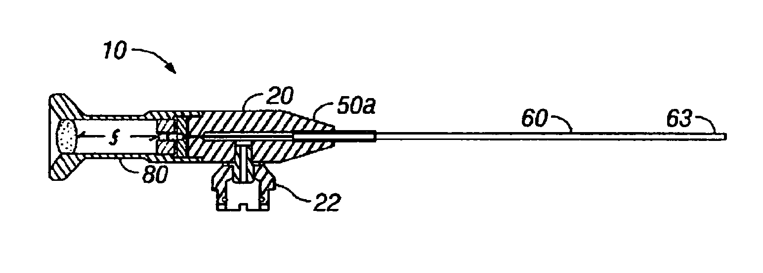
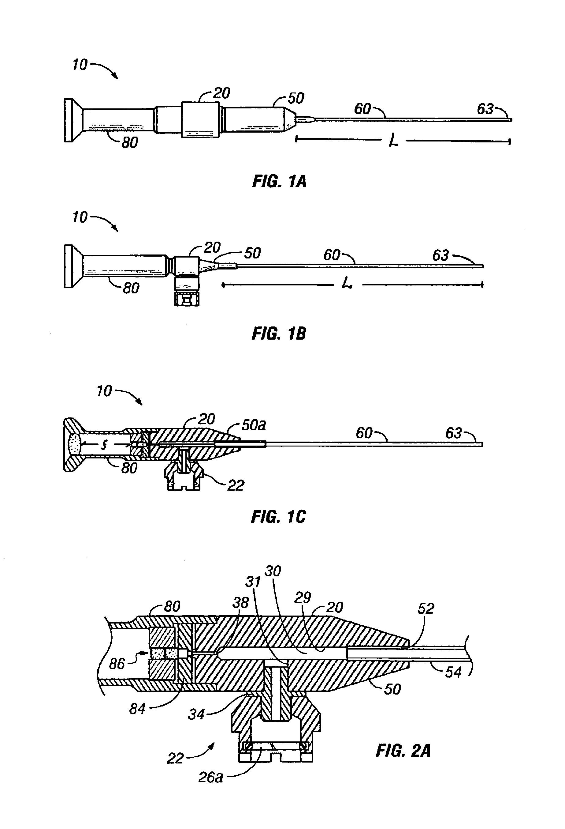
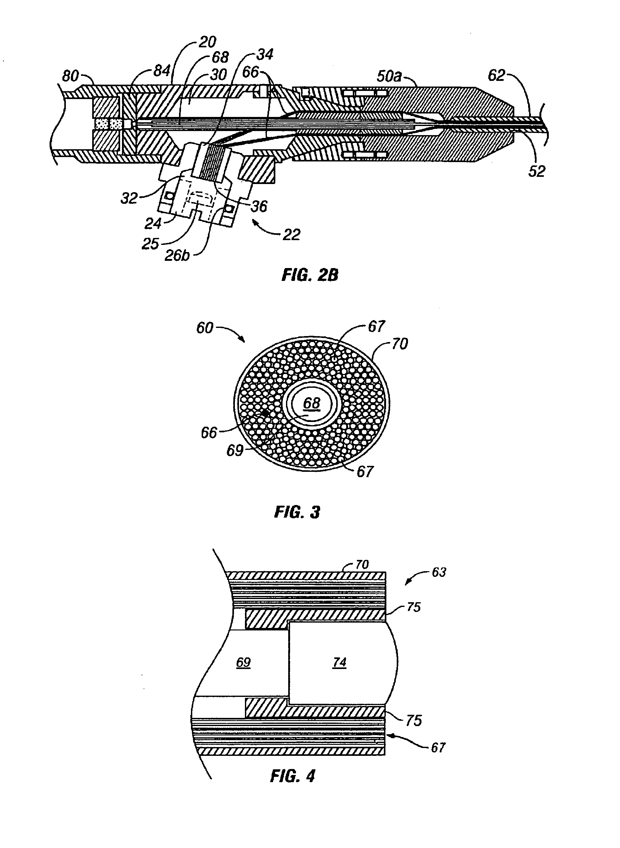
[0037]The present invention is an optical image viewing fiberoptic otoscope 10 as generally illustrated in the figures. The present otoscope is “optical” image viewing in that the user views an optical presentation of a light image through a lens, as opposed to viewing a digital representation of the image reproduced on a view screen. As exemplified in FIGS. 1A to 1C, the main components of the present fiberoptic otoscope 10 include a fiberoptic otoscope body 20, a flexible fiberoptic cable speculum 60 and cable head 50, and an optical image viewer 80. The present invention utilizes existing fiberoptic technologies and incorporates them into a novel optical image viewing otoscope ...


PUM


Abstract

The present optical image viewing fiberoptic otoscope electromagnetically passive. A body portion is connectable to a light source and has mounted to it a fiberoptic cable and an optical viewer. The fiberoptic cable is thin and flexible, and contains separate light and image transmission paths. Its distal end is adapted for emitting and receiving light. The body includes a light source connection for interfacing an external light source. An optical-type image viewer attached to the body is in light communication with the image path for displaying a received image for viewing by a user. One or more tools are mountable to the otoscope body or fiberoptic cable for performing an operation at the distal end of the fiberoptic cable, e.g., removal of a material from the site. Optionally, the otoscope body may be mounted to a headband via an articulated support arm.

Description

[0001]The present application claims the benefit of prior filed U.S. Provisional Application Ser. No. 60 / 532,468 filed 24 Dec. 2003 and to new U.S. Provisional application Ser. No. 60 / 559,223 filed 2 Apr. 2004, to which prior applications the present application is a regular U.S. national application.FIELD OF THE INVENTION[0002]The present invention is in the field of medical instruments useful for illuminating, viewing, diagnosing and removing material from the ear, nose and throat. More specifically, the present invention relates to otoscopes having fiberoptic imaging and illuminating means, and further means for engaging and removing foreign objects or materials.BACKGROUND OF THE INVENTION[0003]A physician's usage of the typical otoscope to perform a diagnostic inspection of a patient's tympanic membrane can be frustrated due to a variety of causes. These include narrow ear canals, excess cerumen and hair that can block the physician's view of the tympanic membrane. With many chi...

Claims


Application Information

Patent Timeline
Patent Type & Authority Patents(United States)
IPC IPC(8): A61B1/06A61B1/227A61B1/267
CPCA61B1/00087A61B1/00195A61B1/227
Inventor PRESCOTT, JAMES T.
Owner MEDICAL INNOVATIONS
Learn More