Force and deflection sensor with shell membrane and optical gratings and method of manufacture

a technology of optical grating and force and deflection sensor, which is applied in the direction of optical radiation measurement, force/torque/work measurement apparatus, instruments, etc., can solve the problem of increasing the strain in one or more passageways where the optical fiber is located

Active Publication Date: 2011-03-08
INTELLIGENT FIBER OPTIC SYST
View PDF19 Cites 35 Cited by
  • Summary
  • Abstract
  • Description
  • Claims
  • Application Information

AI Technical Summary

Problems solved by technology

Deflection of the sensor, such as by a force applied to the contact region, causes an incremental strain in one or more passageways where the optical fiber is located.

Method used


Image

  • Force and deflection sensor with shell membrane and optical gratings and method of manufacture
  • Force and deflection sensor with shell membrane and optical gratings and method of manufacture
  • Force and deflection sensor with shell membrane and optical gratings and method of manufacture

Examples


Embodiment Construction

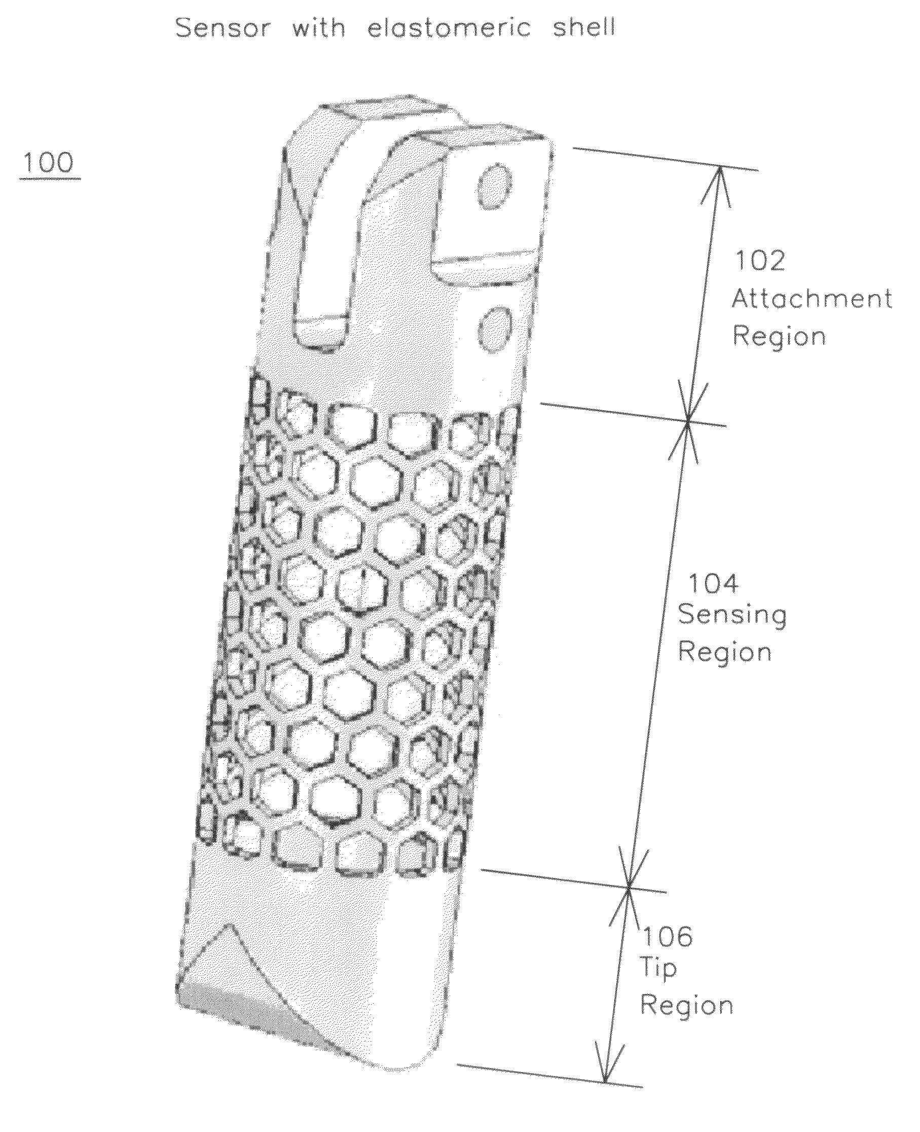
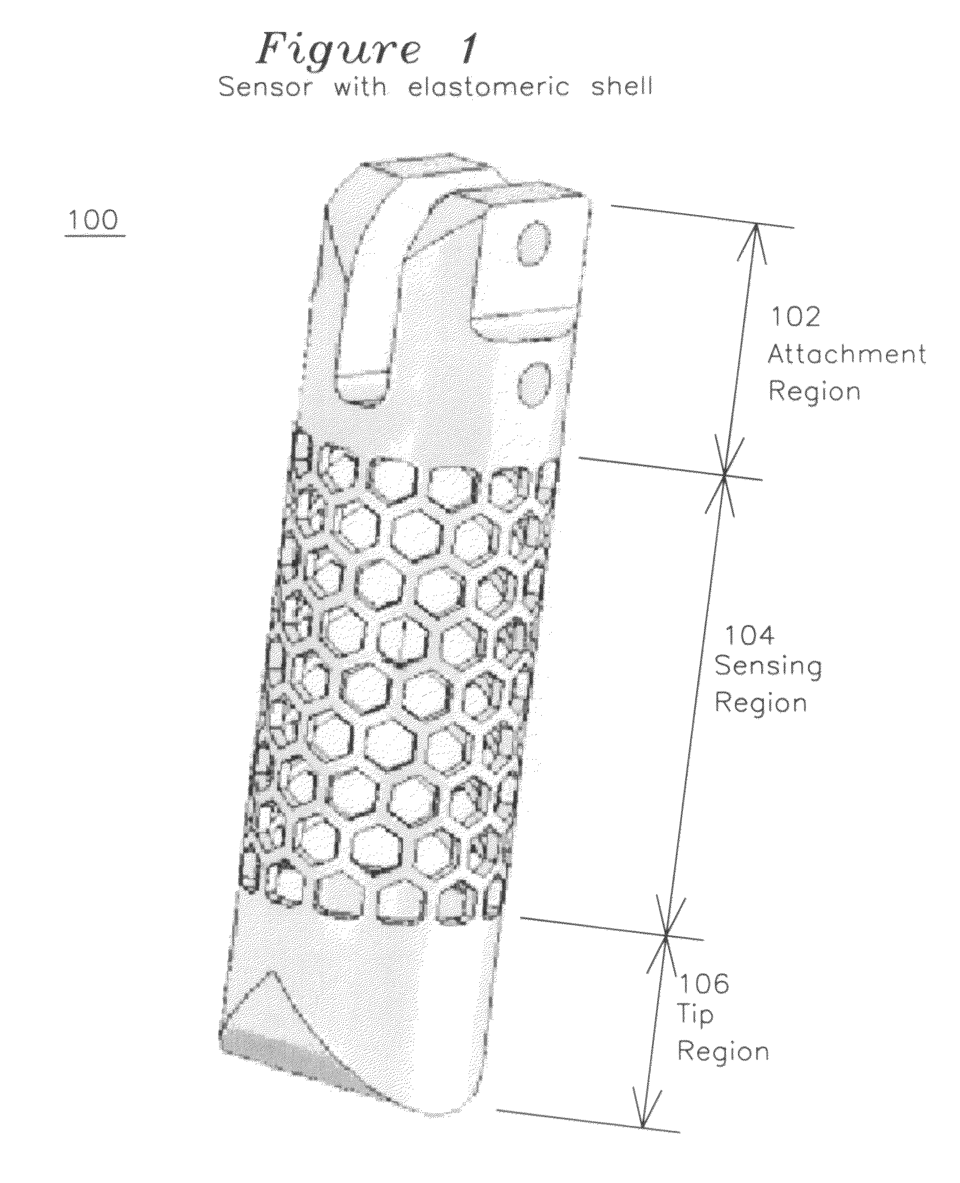
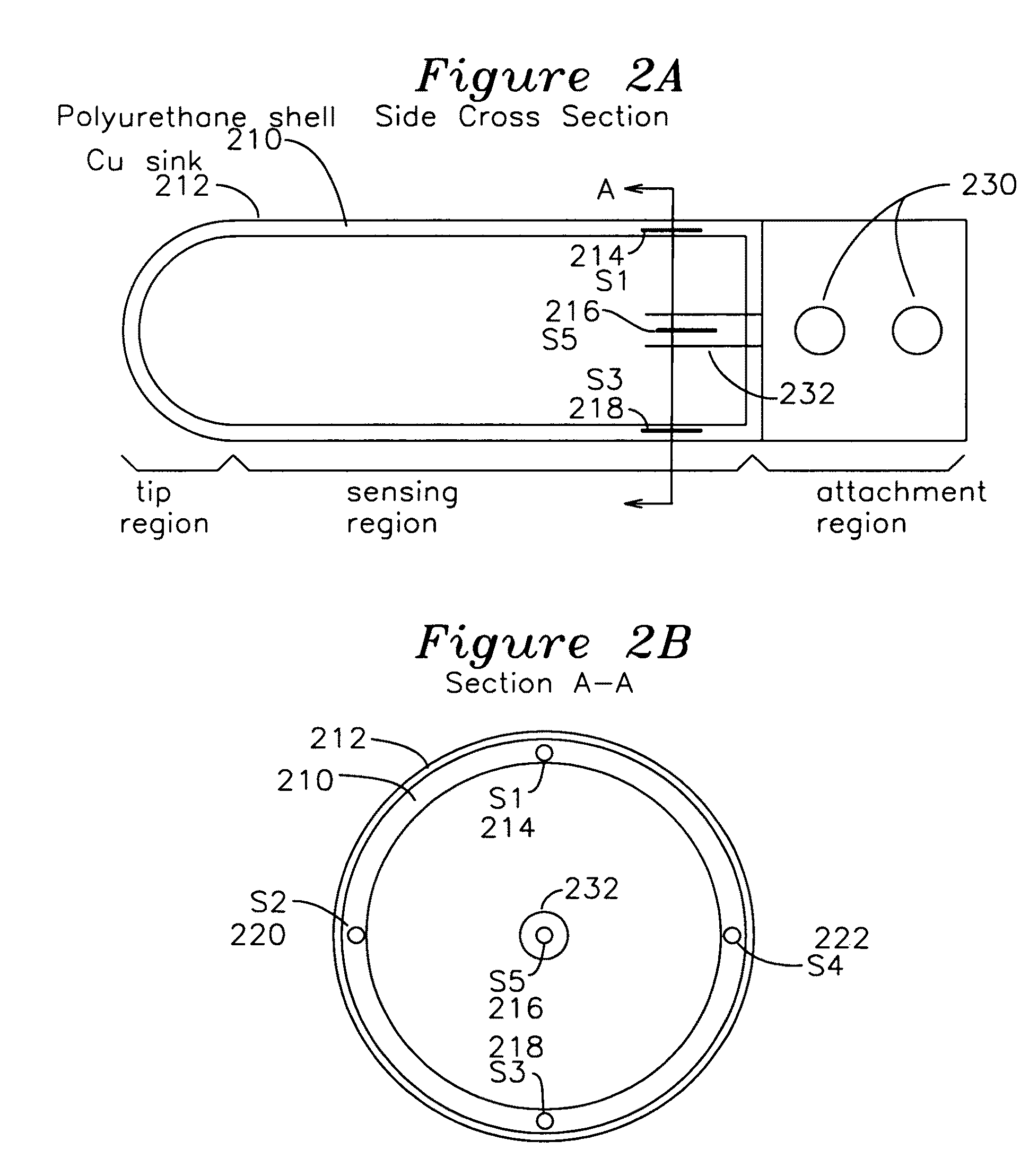
[0025]FIG. 1 shows a perspective view of an example embodiment of a sensor finger 100 having an attachment region 102, a hollow sensing region 104, and a hollow tip region 106. The sensor is not limited in its dimensions, but in one example embodiment, the attachment region extent is approximately 35 mm, the sensing region extent is approximately 65 mm, and the tip region extent is approximately 20 mm with a cylindrical diameter of 35 mm. FIG. 2A shows a simplified cross section view of the sensor of FIG. 1, which includes a polyurethane shell 210 forming the tip region and sensing region, transitioning to a rigid attachment region including mounting holes 230. The shell 210 has a fiber optic cable embedded in it, which may route through passageways of the sensing region and tip region in any manner through the shell 210, and having a plurality of strain sensors formed as Bragg gratings in particular regions such as 214 and 218 of the shell 210. FIG. 2B shows a section A-A of FIG. 2...


PUM

PropertyMeasurementUnit
wavelengthaaaaaaaaaa
temperaturesaaaaaaaaaa

Abstract

A sensor for force is formed from an elastomeric cylinder having a region with apertures. The apertures have passageways formed between them, and an optical fiber is introduced into these passageways, where the optical fiber has a grating for measurement of tension positioned in the passageways between apertures. Optionally, a temperature measurement sensor is placed in or around the elastomer for temperature correction, and if required, a copper film may be deposited in the elastomer for reduced sensitivity to spot temperature variations in the elastomer near the sensors.

Description

[0001]The present invention was developed under National Aeronautics and Space Administration (NASA) Contracts #NNJ05JC02C and NNJ06JA36C. The government has certain rights in this invention.BACKGROUND OF THE INVENTION[0002]1. Field of the Invention[0003]The present invention relates to a force and deflection sensor. In particular, the invention relates to an flexible shell formed with an elastomer having passageways formed by apertures in the shell, with an optical fiber having one or more Bragg gratings positioned in the passageways for the measurement of force and deflection.[0004]2. Description of the Related Art[0005]Future robots are expected to free human operators from difficult and dangerous tasks requiring high dexterity in various environments. One example is an extra-vehicular repair of a manned spacecraft that would otherwise require hazardous work by human astronauts. Another example is robotic surgery in which accurate manipulation is crucial. Operating complicated to...

Claims


Application Information

Patent Timeline
Patent Type & Authority Patents(United States)
IPC IPC(8): G02B6/00G01L19/04G01J1/04
CPCG01D3/0365G01D5/35303G01K11/3206G01L1/246G01L5/166G02B6/022G01D5/35316
Inventor PARK, YONG-LAEMOSLEHI, BEHZADBLACK, RICHARD JAMESCUTKOSKY, MARK R.CHAU, KELVIN K
Owner INTELLIGENT FIBER OPTIC SYST
Why Eureka
Try Eureka