System and method for improved low flow medical pump delivery

a medical pump and low-flow technology, applied in the field of medical pumps, can solve the problems of limiting the accuracy and/or flow continuity of these pumps, unable to provide mechanisms, and unable to determine when the medical pump is actually delivering a substance to a patient,

Active Publication Date: 2011-03-15
ICU MEDICAL INC
View PDF47 Cites 125 Cited by
  • Summary
  • Abstract
  • Description
  • Claims
  • Application Information

AI Technical Summary

Benefits of technology

[0024]One advantage of the present system and method is that the ECRI requirements for an “Excellent” rating are achieved. Specifically, the medical pump delivers a substance in increments or bolus volumes of no greater than two micro-liters at a flow rate of 0.1 milliliter per hour, with “no-flow” periods of less than 20 seconds f. Another advantage of the present invention is that each step of the delivery of the substance is consistent within a small error margin.

Problems solved by technology

Conventional pumps, in general, rely on nominal or empirical data to estimate the delivery volumes and delivery rates, and do not provide mechanisms for adjusting an actual delivery due to variations from this nominal or empirical data.
This lack of adjustment during an actual delivery limits the accuracy and / or flow continuity of these pumps.
In addition, medical pumps are operated at low flow rates, such as below 1 mL / hr or less, the determination of when the medical pump is actually delivering a substance to a patient can be difficult.
It has been found that sensed data can provide false indications that actual delivery of the substance, such as the flow of a fluid, is occurring.
Other potential difficulties occur when attempting to use traditional medical pumps at low flow rates, without using specialty items such as specialty neonatal cassettes.
In particular, mechanical friction and / or electrical noise can also trigger false data indicating that the delivery has actually begun, inducing periods of no flow.

Method used


Image

  • System and method for improved low flow medical pump delivery
  • System and method for improved low flow medical pump delivery
  • System and method for improved low flow medical pump delivery

Examples


Embodiment Construction

[0041]While this invention is susceptible of embodiments in many different forms, there is shown in the drawings and will herein be described in detail preferred embodiments of the invention with the understanding that the present disclosure is to be considered as an exemplification of the principles of the invention and is not intended to limit the invention to the embodiments illustrated.

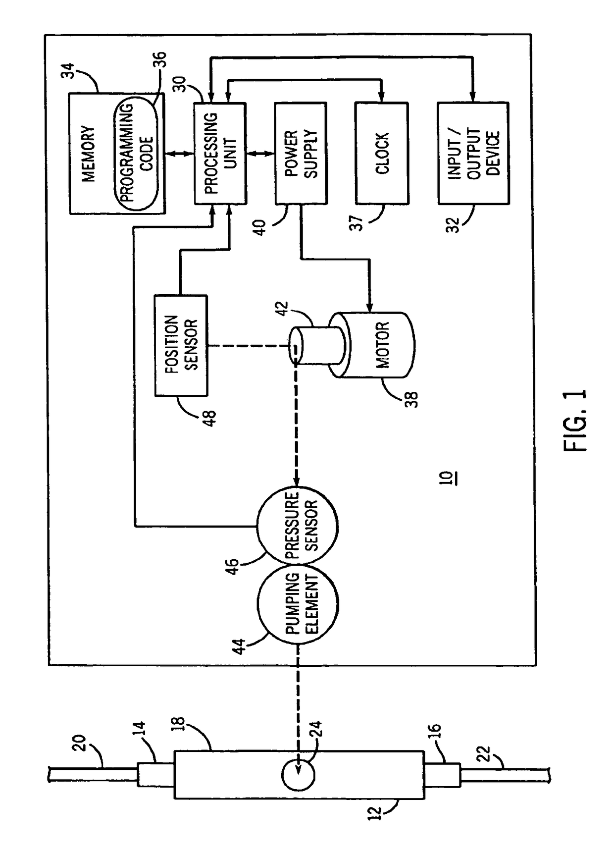
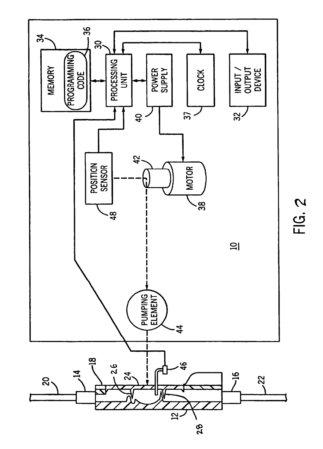
[0042]A medical pump includes but is not limited to enteral pumps, infusion pumps, cassette pumps, syringe pumps, peristaltic pumps, or any positive displacement fluid pumping device for the delivery of fluids intravenously or intra-arterially to a patient. Referring initially to FIG. 1, one embodiment of a medical pump 10 is provided in connection with a disposable pumping chamber, such as a cassette 12 or tube, for delivering a substance, such as a fluid, to a patient. In various embodiments of the medical pump of the present invention, the pumping chamber is a portion of at least one of a casse...


PUM


Abstract

A medical pump with an improved continuity low flow delivery system and method for use with a pumping chamber, for example in a cassette, is disclosed. The pump includes a pump drive for exerting a force on the pumping chamber and a sensor for sensing the force / pressure exerted by the pump drive on the pumping chamber. The pump drive position sensor senses the position of the pump drive. The medical pump also includes a processing unit and a memory having a programming code adapted to calculate the rate of change of the sensed force / pressure values and determine whether the rate of change of the sensed force / pressure values meets a rate of change threshold. Once the rate of change threshold is met, the programming code is adapted to calculate a remaining pump drive travel value for determining how much farther the pump drive should travel before the end of an effective pump cycle. The programming code is further adapted to trigger one or more signals to drive the pump drive for the remainder of the effective pump cycle using the remaining pump drive travel value.

Description

CROSS-REFERENCE TO RELATED APPLICATIONS[0001]This application is a continuation-in-part of U.S. patent application Ser. No. 10 / 810,123, filed Mar. 26, 2004.FEDERALLY SPONSORED RESEARCH OR DEVELOPMENT[0002]None.TECHNICAL FIELD[0003]The invention relates to medical pumps for delivering a substance, such as a fluid to a patient. In particular, the present invention relates to medical pumps which provide low flow delivery of a substance to a patient.BACKGROUND OF THE INVENTION[0004]Modern medical care often involves the use of medical pump devices to deliver substances, such as fluids and / or fluid medicine to patients. Medical pumps permit the controlled delivery of substances to a patient, and such pumps have largely replaced gravity flow systems, primarily due to the pump's much greater accuracy in delivery rates and dosages, and due to the possibility for flexible yet controlled delivery schedules.[0005]A typical positive displacement pump system includes a pump device driver and a d...

Claims


Application Information

Patent Timeline
Patent Type & Authority Patents(United States)
IPC IPC(8): F04B49/00A61M1/00G05D7/00F04B43/12A61M5/142A61M5/168A61M5/172
CPCA61M5/14224A61M5/16809A61M5/172A61M5/16854A61M2205/128A61M2205/3331
Inventor WANG, DAVID T.SCARAMUZZI, PETER J.SALEKI, MANSOUR A.COUSINEAU, ROBERT P.ABRAHAMSON, KENT D.LAWLESS, MICHAEL W.FATHALLAH, MARWAN A.KIDD, BRIAN A.BOYD, ROBERT R.GREENE, HOWARD L.NAVIN, ERIC R.LUCKE, LORI E.MULLIN, BENJAMIN T.
Owner ICU MEDICAL INC
Why Eureka
Try Eureka