Support system for auxiliary power unit

a technology for supporting systems and power units, applied in the field of supporting systems, can solve the problems of complex and costly manufacturing and assembly process, costly repair,

Active Publication Date: 2011-03-22
AIRBUS OPERATIONS SL
View PDF7 Cites 10 Cited by
  • Summary
  • Abstract
  • Description
  • Claims
  • Application Information

AI Technical Summary

Benefits of technology

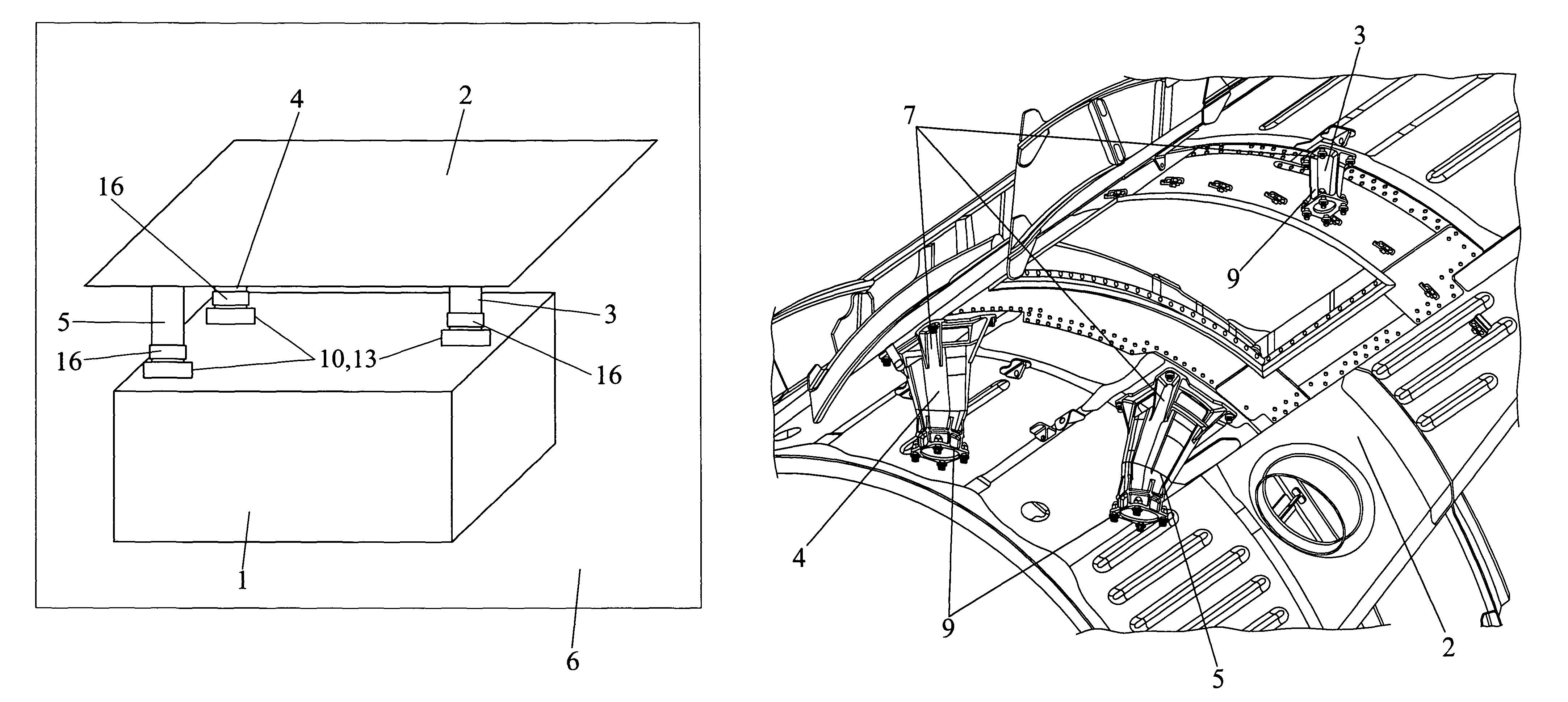
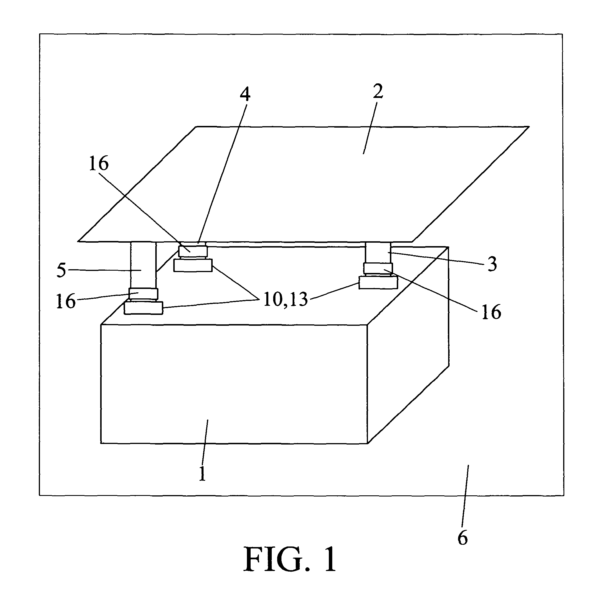
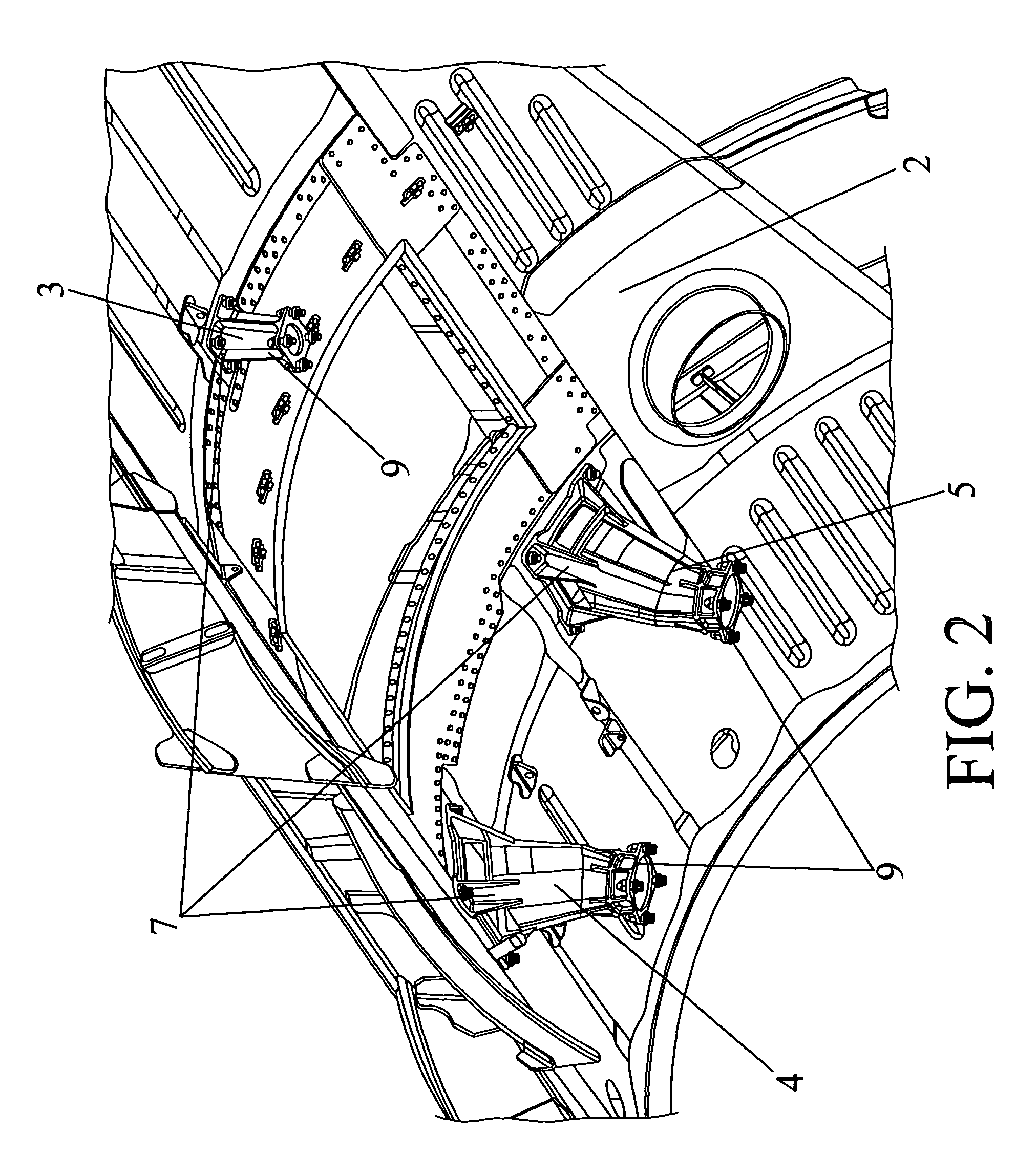
[0009]The present invention has the aim of overcoming the drawbacks of the state of the art pointed out above by means of an support system for auxiliary power unit for an aircraft. The objective of this invention is the perfect securing of the auxiliary power unit of an aircraft in the interior of the chamber where said auxiliary power unit is housed, along with improving the behaviour towards fatigue of currently existing structures, and facilitating their maintenance.
[0010]Said support system for auxiliary power unit comprises a set of at least three fittings made of an ignition resistant material, in order to prevent those fittings from being able to catch fire so that they can support the loads required in the event of fire, and also for being able to withstand the high temperatures that can be reached in the vicinity of the auxiliary power unit, without losing any of their properties.
[0011]The fittings present a shape that is frustro-conical. The main advantage of this geometry is ease of manufacture, plus the elimination of edges where stresses can accumulate and cause the fittings to break.

Problems solved by technology

The drawback of these conventional systems is precisely their complexity and their size, which gives rise to a complex and costly manufacturing and assembly process, with a large number of pieces being used, in addition to creating difficult access to the auxiliary power unit compartment for inspection and maintenance, both of the auxiliary power unit and of the support system itself, as well as costly repair when this support system deteriorates.

Method used


Image

  • Support system for auxiliary power unit
  • Support system for auxiliary power unit
  • Support system for auxiliary power unit

Examples


Embodiment Construction

[0009]The present invention has the aim of overcoming the drawbacks of the state of the art pointed out above by means of an support system for auxiliary power unit for an aircraft. The objective of this invention is the perfect securing of the auxiliary power unit of an aircraft in the interior of the chamber where said auxiliary power unit is housed, along with improving the behaviour towards fatigue of currently existing structures, and facilitating their maintenance.

[0010]Said support system for auxiliary power unit comprises a set of at least three fittings made of an ignition resistant material, in order to prevent those fittings from being able to catch fire so that they can support the loads required in the event of fire, and also for being able to withstand the high temperatures that can be reached in the vicinity of the auxiliary power unit, without losing any of their properties.

[0011]The fittings present a shape that is frustro-conical. The main advantage of this geometr...


PUM


Abstract

Support system suitable for sustaining an auxiliary power unit of an aircraft to a fixed structure (2) belonging to a compartment of the auxiliary power unit (6) of the aircraft. The support system is made in a high mechanical strength material and with high resistance to ignition, and comprises three fittings (3, 4, 5) two of which are frusto-conical and one with a substantially cylindrical. Fittings (3, 4, 5) being able to be hollow and being able to comprise an array of lateral ribs. Each one of them presenting a first end (7) comprising means of attachment of the support system (8) to the fixed structure (2) and a second end (9) comprising means of securing of the support system (8) which are joined to the auxiliary power unit (1) in the periphery of the extension of said auxiliary power unit (1).

Description

CROSS REFERENCE TO RELATED APPLICATIONS[0001]The present application claims priority from Spanish Application Serial No. P200502626, filed on Oct. 28, 2005. Applicants claim priority under 35 U.S.C. §119 as to the said Spanish application, and the entire disclosure of said application is incorporated herein by reference in its entirety.FIELD OF THE INVENTION[0002]This invention belongs to the field of support systems for large and heavy pieces, said support systems presenting characteristics of high mechanical strength and high resistance to ignition. In particular, the invention applies to the sector of support system for auxiliary power units employed in the aeronautical sector.STATE OF THE ART PRIOR TO THE INVENTION[0003]In the field of aeronautics, the auxiliary power unit is usually located in the tail of the aircraft and can weigh more than 600 kg. Also, owing to the operation of that engine, high temperatures can be reached in the compartment where it is housed, up to 200° C....

Claims


Application Information

Patent Timeline
Patent Type & Authority Patents(United States)
IPC IPC(8): B64D41/00
CPCB64D27/26B64D41/00B64D2041/002Y02T50/44Y02T50/40
Inventor MARTINEZ RUEDA, JOSE ROMANROJO CARRION, JOSE ALBERTOSEN PACIOS, JOSE LUISMELIAN BRINQUIS, JUAN PABLOROJO SAIZ, NICOLASMARTIN CALVO, DAVIDTHOMAS, STEFFAN PRYSMARQUEZ GAVILAN, ANTONIOGARCIA PATINO, MARIA ARANZAZU
Owner AIRBUS OPERATIONS SL
Why Eureka
Try Eureka