Stratum deployment of wind turbines

a technology of wind turbines and strata, which is applied in the direction of wind turbines with perpendicular air flow, wind turbines with parallel air flow, wind energy generation, etc., can solve the problems of noise and size of wind turbines, affecting scenic and habitat conditions, and existing conventional uses have certain limitations in distribution and deployment, so as to achieve convenient installation and stable and consistent infrastructure

Inactive Publication Date: 2011-03-22
TAMIRAS PER PTE LTD LLC
View PDF68 Cites 17 Cited by
  • Summary
  • Abstract
  • Description
  • Claims
  • Application Information

AI Technical Summary

Benefits of technology

In contrast, small-sized wind turbines used in isolated areas for private homes, businesses, and individuals are a great way to introduce clean energy on a unit-by-unit grass roots level. Furthermore, small-sized wind turbines can be easily connected to multiple direct sources or various grid interconnection points for distribution.
Accordingly, a method and corresponding apparatus for maximizing the wind energy gathering potential of a plurality of wind turbines for a given location, each wind turbine having a sweep height, includes sizing the sweep heights of substantially all wind turbines of the plurality of wind turbines to intersect at least one horizontal plane unique from horizontal planes intersected by a sweep height of at least one immediately adjacent wind turbine.

Problems solved by technology

Unfortunately, existing conventional uses have certain limitations in distribution and deployment.
Acceptance of large-sized wind turbines is faced with several challenges.
For example, environmentalists fear that the noise and size of wind turbines will disrupt both scenic and habitat conditions.
Also of environmental concern is the threat to the well being of birds that may be caught in the blades of large wind turbines.
The United States Department of Defense too has voiced its concern that large-sized wind turbines interfere with radar signals and tracking.

Method used


Image

  • Stratum deployment of wind turbines
  • Stratum deployment of wind turbines
  • Stratum deployment of wind turbines

Examples


Embodiment Construction

A description of example embodiments of the invention follows.

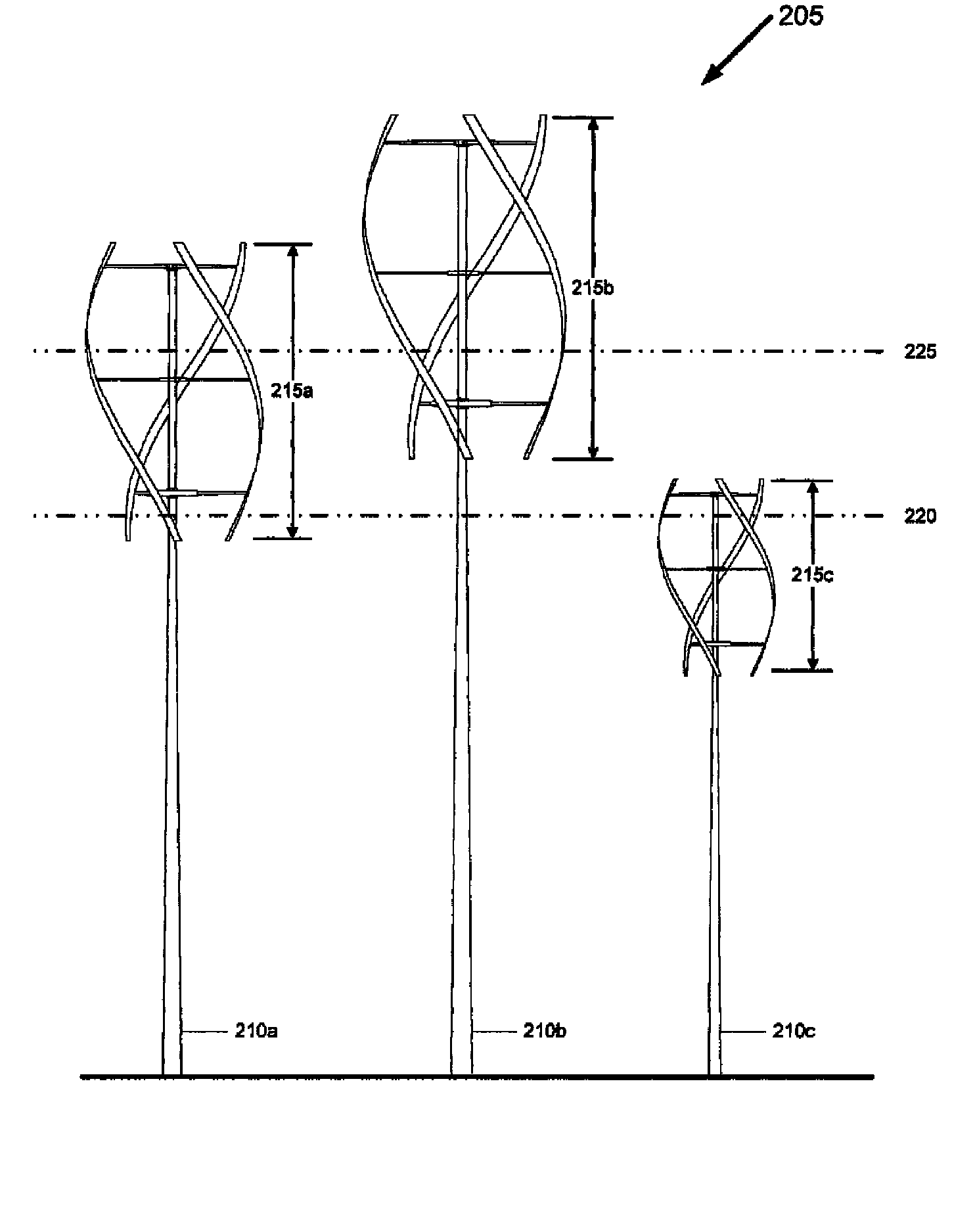
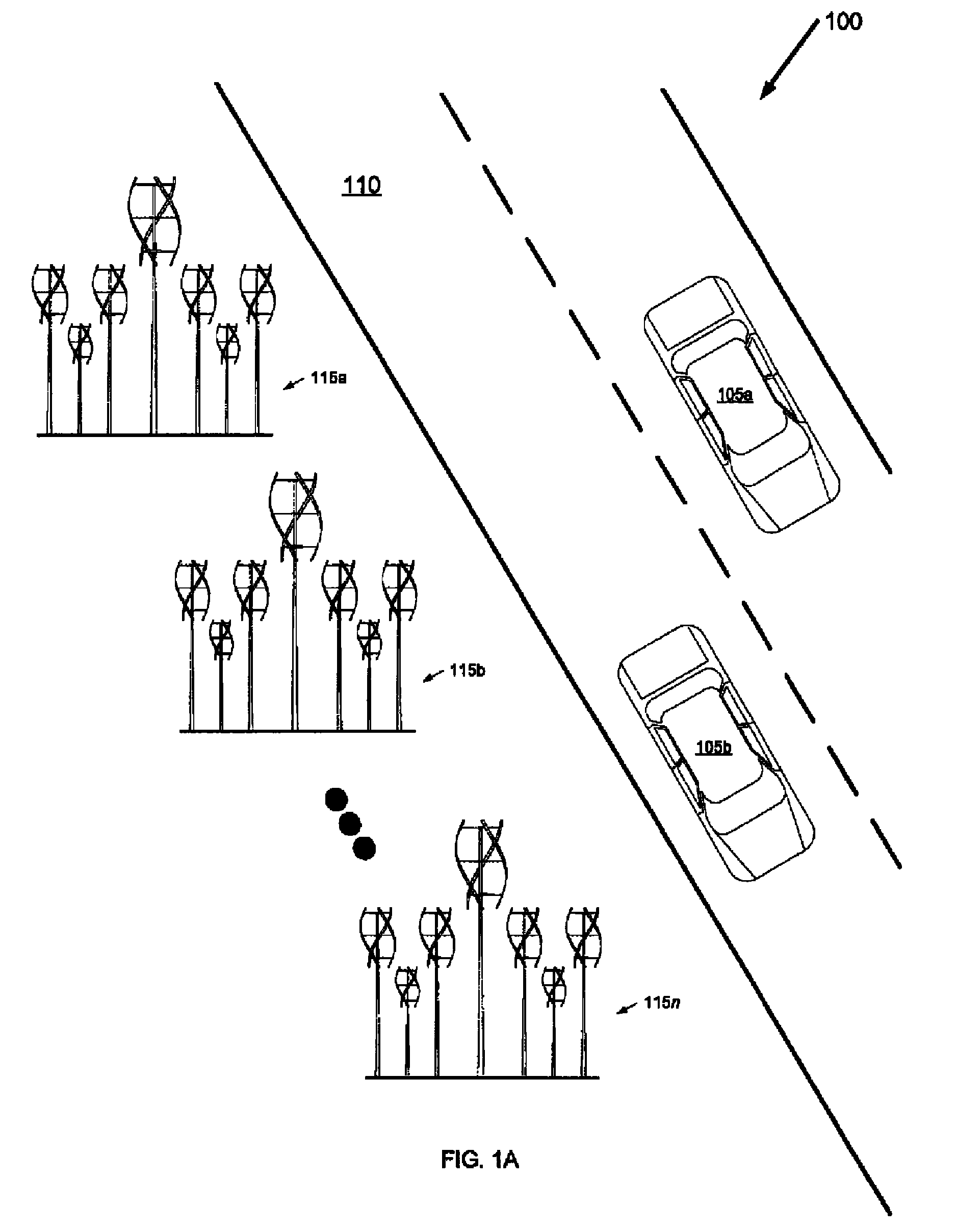
In FIG. 1A, in an example roadway system 100 for wind energy generation and distribution, vehicles 105a and 105b (e.g., an automobile, truck, etc.) travel along a roadway 110 (e.g., a road, highway, etc.). Situated or otherwise located alongside the roadway 110 are a plurality of wind turbines 115a, 115b, . . . 115n (generally 115). The plurality of wind turbines 115 gather wind energy from or created by a variety of sources.

For example, being situated alongside the roadway 110, the plurality of wind turbines 115 gather wind energy created by the vehicles 105a and 105b moving by the plurality of wind turbines 115 and causing air to move (so called, “dirty wind”).

In another example, the plurality of wind turbines 115 gathers naturally occurring wind energy (e.g., atmospheric wind). In this way, wind energy is gathered (and thus wind generated energy is generated) even when there are no vehicles traveling along the roadway ...


PUM


Abstract

Installing large-sized wind turbines creates numerous challenges and limitations, hindering acceptance of wind generated energy. With small-sized wind turbines, such hindrances are omitted or minimized. Sized ever smaller, more small-sized wind turbines may be installed per installation. Accordingly, a method and corresponding apparatus for maximizing wind energy gathering potential of a plurality of wind turbines, each wind turbine having a sweep height, for a given location is provided. The present invention includes sizing sweep heights of substantially all wind turbines of the plurality of wind turbines to intersect at least one horizontal plane unique from horizontal planes intersected by a sweep height of at least one immediately adjacent wind turbine. Because the sweep height of each wind turbine of the plurality is individually sized in a prescribed manner, the present invention maximizes the wind energy gathering potential of the plurality of wind turbines especially for deployment of small-sized wind turbines.

Description

BACKGROUND OF THE INVENTIONA wind-powered turbine, or simply wind turbine, generates electrical power, which can be delivered to an existing electricity grid system via an interconnection or which may be used to directly power an individual home, business or utility. Wind turbines used to gather large amounts of power (e.g., in the megawatt range) are large structures, typically 100 feet high or higher.SUMMARY OF THE INVENTIONCurrently, installations of large-sized wind turbines, on the order of 100 feet or more, dot the landscape of the planet. These large-sized wind turbines are often located in remote fields, out to sea, or on private property away from public infrastructure.Installations of small-sized wind turbines and other wind energy gathering devices, in the 5 to 30 foot range, are typically utilized in one of three deployments. The first deployment features clusters of small to mid-sized wind turbines set up in remote windy areas, such as, the desert environment near Palm ...

Claims


Application Information

Patent Timeline
Patent Type & Authority Patents(United States)
IPC IPC(8): F03D3/02
CPCF03D9/007F03D9/021F05B2220/61F05B2240/212F05B2240/9113F05B2240/941F05B2250/25F05B2250/82Y02B10/30Y02E70/10Y02E10/728Y10S415/907F03D9/11F03D9/46F03D9/257Y02E10/72Y02E60/36Y02E70/30
Inventor FEIN, GENE S.MERRITT, EDWARD
Owner TAMIRAS PER PTE LTD LLC
Why Eureka
Try Eureka