System and Method for Creating Micro/Nano Wind Energy Gathering Devices

Active Publication Date: 2008-06-26
TAMIRAS PER PTE LTD LLC
View PDF44 Cites 37 Cited by
  • Summary
  • Abstract
  • Description
  • Claims
  • Application Information

AI Technical Summary

Benefits of technology

[0016]It should be noted that the production and assembly modules may produce and assemble a plurality of components in parallel, and the system may include a mounting module that mounts a plurality of the wind energy ga

Problems solved by technology

Existing conventional uses of wind turbines have certain limitations in distribution and deployment, and large turbines have faced environmental and Defense Department concerns.
Environmentalists fear that the noise and size of turbines will disrupt both scenic and habitat conditions in addition to threaten the well being of birds that may be caught in the large turbine blades.
The Department of Defense has raised concerns over the possible interference of the large turbines with radar signals and tracking.
Large turbine systems that are placed far away from existing infrastructure also incur a large expense in the transportation or building of infrastructure to carry the power generated by the turbine system.
Finally, the large turbine system represents a major, volatile investment for a single turbine.
If wind is not present or wind currents change, then the turbine would be viewed as a poor investment because it will not generate enough power to be profitable.
Furthermore, if the turbine breaks for any reason, it will produce zero power as it is a large and single entity.
Large turbines also require labor intensive maintenance and monitorin

Method used


Image

  • System and Method for Creating Micro/Nano Wind Energy Gathering Devices
  • System and Method for Creating Micro/Nano Wind Energy Gathering Devices
  • System and Method for Creating Micro/Nano Wind Energy Gathering Devices

Examples


Embodiment Construction

[0022]A description of example embodiments of the invention follows.

[0023]“Wind” as used herein refers to both wind created by the movement of vehicles (hereinafter also “dirty wind”) and atmospheric wind.

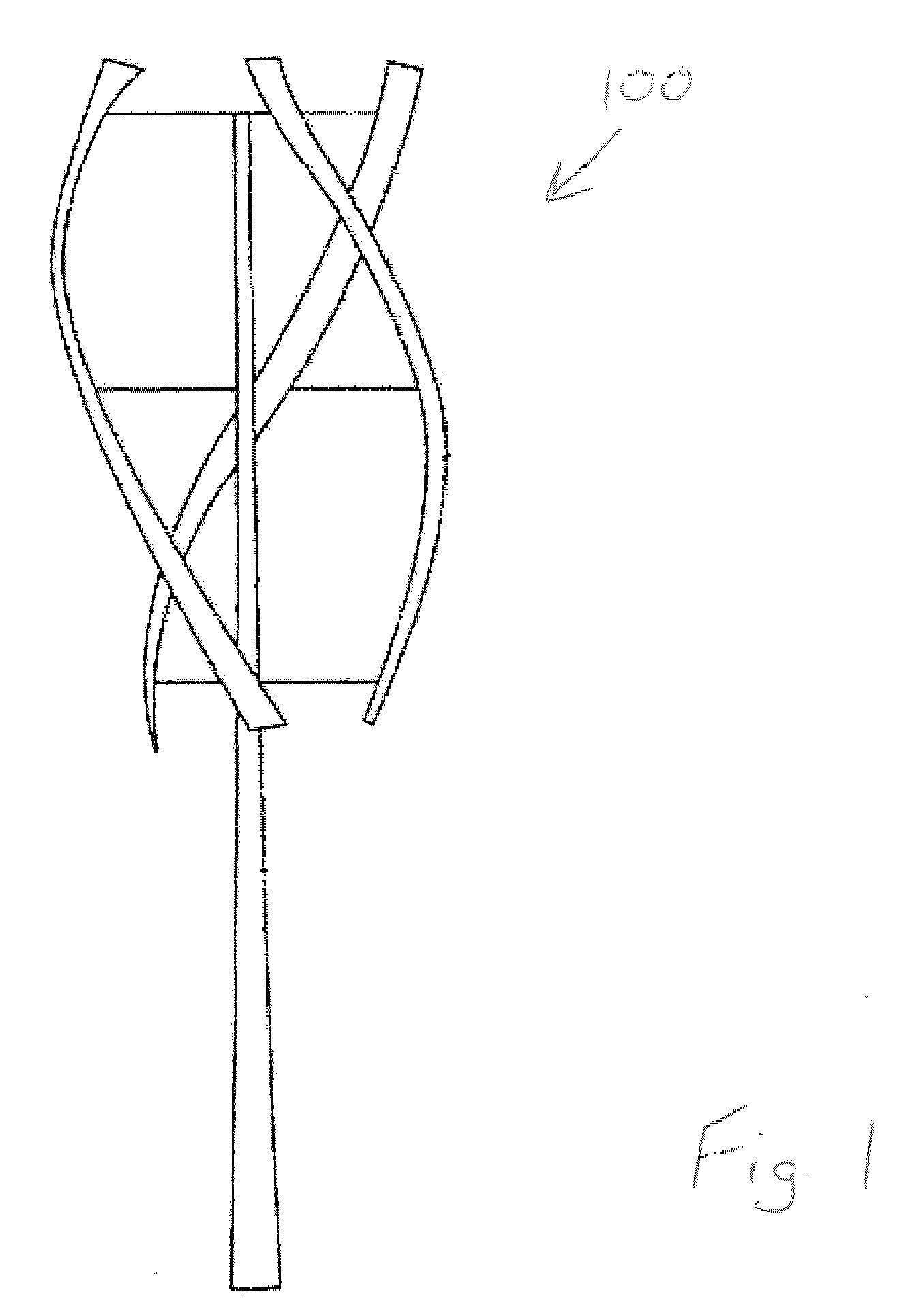
[0024]A “wind energy gathering device” as used herein, is a device that converts wind energy into electrical energy. Wind energy gathering devices may include one or more “wind turbine generators.” A “wind turbine generator” (also “wind turbine” as referred to herein) is a device that includes a turbine and a generator, wherein the turbine gathers or captures wind by conversion of some of the wind energy into rotational energy of the turbine, and the generator generates electrical energy from the rotational energy of the turbine. An example wind turbine generator is illustrated in FIG. 1. These wind turbine generators 100 can employ a turbine rotating around an axis oriented in any direction. For example, in a “horizontal axis turbine,” the turbine rotates around a horizontal axis ...


PUM

PropertyMeasurementUnit
Compositionaaaaaaaaaa
Flow rateaaaaaaaaaa
Dimensionaaaaaaaaaa

Abstract

Method and system for manufacturing small wind energy gathering devices, for example, of geometrical dimensions tip to ⅛th of an inch (microdevices), employing micro-fabrication techniques. For example, three-dimensional single chemical composition parts of a small wind energy gathering device are manufactured using two-photon three dimensional lithography. Preferably, a plurality of such parts are manufactured in parallel, thereby optimizing the production process. The plurality of parts may be handled and assembled using precision instruments such as micro-tweezers, micro-scissors, and holographic lasers. Nanowires may be used to interconnect a plurality of the microdevices together, or to connect components of a particular microdevice. These nanowires are produced in nanowire arrays and are attached to a common base structure. Additionally, a form of injection molding and polymer materials may be utilized in the manufacturing of the small wind energy gathering devices (microdevices), which provide protective coatings and surfaces of reduced friction.

Description

RELATED APPLICATIONS[0001]This application is a continuation-in-part of U.S. application Ser. No. 11 / 627,404, filed Jan. 26, 2007, which is a continuation-in-part of U.S. application Ser. No. 11 / 645,109, filed Dec. 22, 2006. The entire teachings of the above applications are incorporated herein by reference.BACKGROUND OF THE INVENTION[0002]It is well known that wind power turbines can generate power that can be delivered via interconnection to existing grid systems or can be used to power individual homes, businesses, and utilities. Most, if not all, wind power systems that are used to gather large amounts (in the megawatt range) of power are large-structure wind turbines, many of which are at least one-hundred feet high. In the past, smaller wind powered turbines have also been placed high up from the ground, usually at least fifteen feet high. Additionally, most smaller wind power turbine systems are utilized to power a single home, business, or components of that home or business...

Claims


Application Information

Patent Timeline
IPC IPC(8): H05K13/04B21K25/00B82B3/00F03D9/00
CPCB82Y15/00F03D3/005F05B2240/212F05B2250/25F05B2250/82F05B2250/84Y10T29/4932Y02E10/74Y10T29/49009Y10T29/5313Y10T29/4913Y10T29/49002Y02B10/30Y02P70/50
Inventor FEIN, GENE S.MERRITT, EDWARD
Owner TAMIRAS PER PTE LTD LLC
Why Eureka
Try Eureka