Electrical connector with two grooves dividing contacts
What is Al technical title?
Al technical title is built by PatSnap Al team. It summarizes the technical point description of the patent document.
a technology of electrical connectors and grooves, applied in the direction of two-part coupling devices, coupling device connections, electric discharge tubes, etc., to achieve the effect of high transfer speed
Inactive Publication Date: 2011-03-22
HON HAI PRECISION IND CO LTD
View PDF6 Cites 39 Cited by
Summary
Abstract
Description
Claims
Application Information
AI Technical Summary
This helps you quickly interpret patents by identifying the three key elements:
Problems solved by technology
Method used
Benefits of technology
[0009]Accordingly, an object of the present invention is to provide electrical connectors providing interfaces compatible with internal micro Serial ATA connectors with higher transfer speed comparing the internal micro Serial ATA specification.
Problems solved by technology
However, the market demands new interfaces to increase the transfer speed of the micro SATA specification and compatible with the micro SATA plug and incompatible with micro SATA backplane.
Method used
Image
Click on the blue label to locate the original text in one second.
Reading with bidirectional positioning of images and text.
Examples
Embodiment Construction
[0018]Reference will now be made in detail to the preferred embodiment of the present invention.
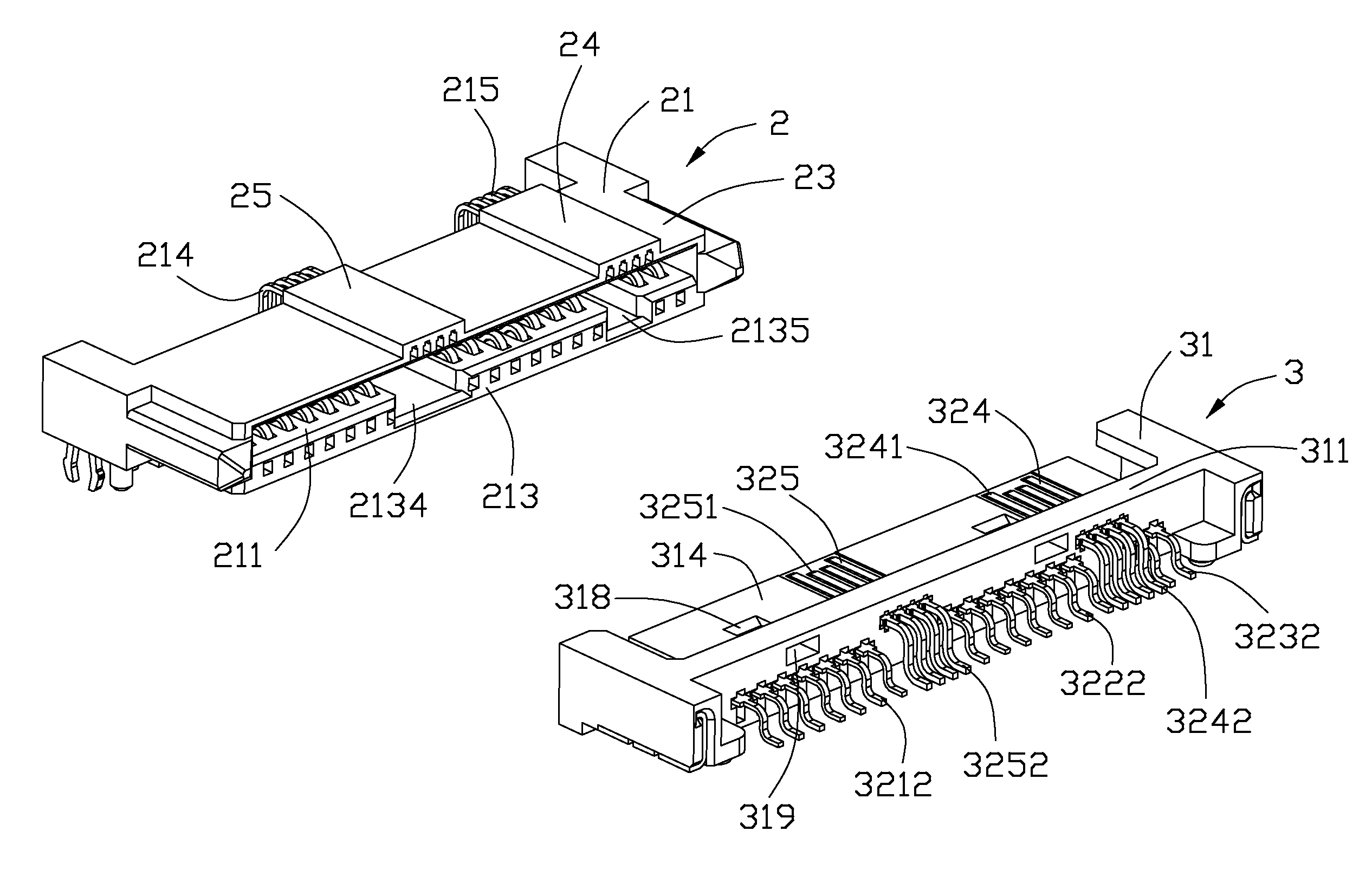
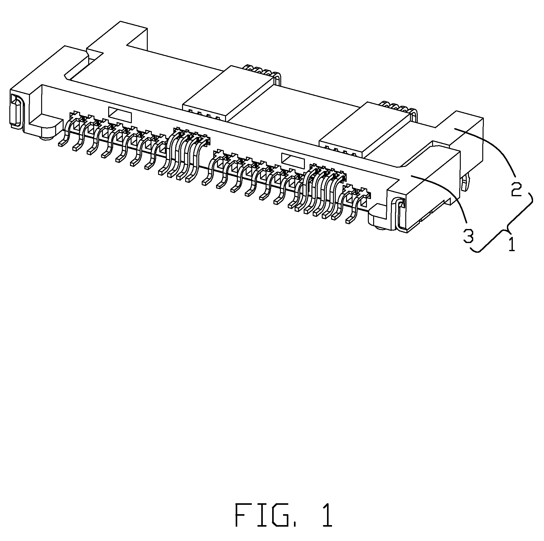
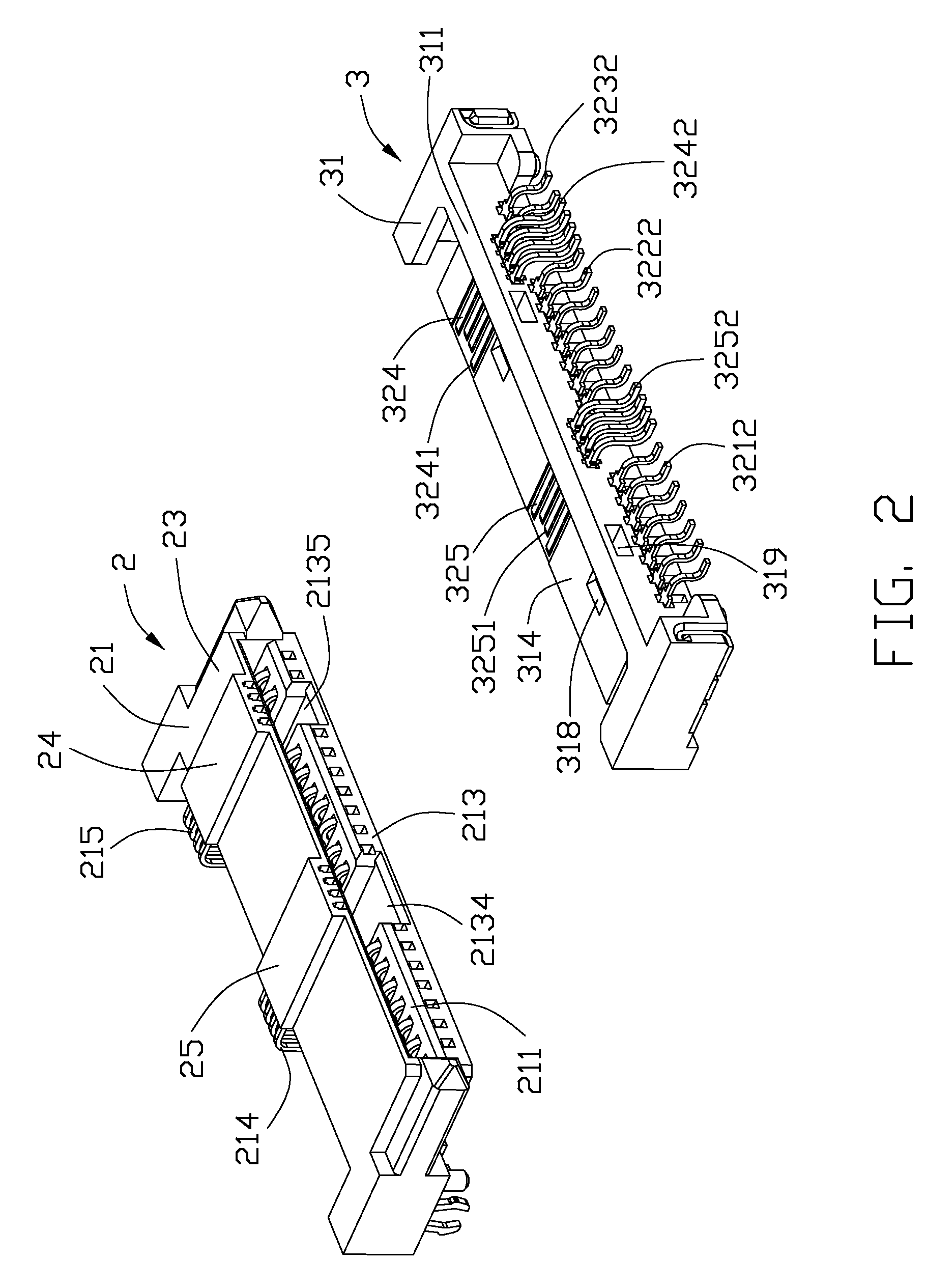
[0019]Referring to FIGS. 1-3, an electrical connector assembly 1 according to the present invention is shown. The electrical assembly 1 includes a first electrical connector 2 to be mounted on a first circuit board (not shown) and a second electrical connector 3 mounted on a second circuit board (not shown). The electrical connectors 100, 200 are used for providing interfaces for a storage device.
[0020]Referring to FIGS. 2-4, the first electrical connector 2 comprises a first insulated housing 21 defining a front face 213 and a first plurality of contacts S1-S7, P1-P9 assembled to the first insulated housing 21. The first insulated housing 21 defines a longitudinal slot 211 in the front face 213, the slot 211 having a first and a second inner side faces (not labeled) facing to each other, and the first and second inner side faces extending in a first direction perpendicular to the front f...
PUM
Abstract
An electrical connector (2, 3) provides an interface compatible with an internal micro Serial ATA connector. The electrical connector (2, 3) includes an insulated housing (21, 31), a first number of contacts (221, 222, 223, 321, 322, 323) assembled to the insulated housing (21, 31); and a second number of contacts (224, 225, 324, 325) assembled to the insulated housing (21, 31). The first number of contacts (221, 222, 223, 321, 322, 323) constitute a power segment and a signal segment compatible with the internal micro Serial ATA connector. The second number of contacts (224, 225, 324, 325) is used for mating with a new type of mating connector (3, 2) when higher transfer speed is needed.
Description
CROSS-REFERENCE TO RELATED APPLICATIONS[0001]The subject matter disclosed herein is related to the subject matter disclosed in pending U.S. patent application Ser. No. 12 / 288,143, filed on Oct. 16, 2008 and entitled “ELECTRICAL CONNECTORS FOR STORAGE DEVICE”, which is assigned to the same assignee as this application.BACKGROUND OF THE INVENTION[0002]1. Field of the Invention[0003]The present invention generally relates to an electrical connector, and more particularly to an electrical connector providing an interface for a storage device.[0004]2. Description of Related Art[0005]The Serial ATA International Organization published a proposed Serial ATA draft specification of revision 0.70 on 21 Sep. 2006. The Serial ATA draft specification disclosed an internal micro Serial ATA plug connector (hereinafter the Micro SATA plug) and an internal micro Serial ATA backplane connector (hereinafter the Micro SATA backplane) for mating with the Micro SATA plug in Pages 101-109.[0006]The micro ...
Claims
Application Information
Patent Timeline
Application Date:The date an application was filed.
Publication Date:The date a patent or application was officially published.
First Publication Date:The earliest publication date of a patent with the same application number.
Issue Date:Publication date of the patent grant document.
PCT Entry Date:The Entry date of PCT National Phase.
Estimated Expiry Date:The statutory expiry date of a patent right according to the Patent Law, and it is the longest term of protection that the patent right can achieve without the termination of the patent right due to other reasons(Term extension factor has been taken into account ).
Invalid Date:Actual expiry date is based on effective date or publication date of legal transaction data of invalid patent.