
Input regulated DC to DC converter for power scavenging
a technology of input voltage, which is applied in the direction of electric variable regulation, process and machine control, instruments, etc., can solve the problems of excessive voltage drop across the input terminal, unfit dc to dc converters for some applications requiring voltage conversion, and unregulated voltage across the input terminal of available dc to dc converters
Patent Information
- Authority / Receiving Office
- US · United States
- Patent Type
- Patents(United States)
- Current Assignee / Owner
- Publication Date
- 2011-03-22
Smart Images
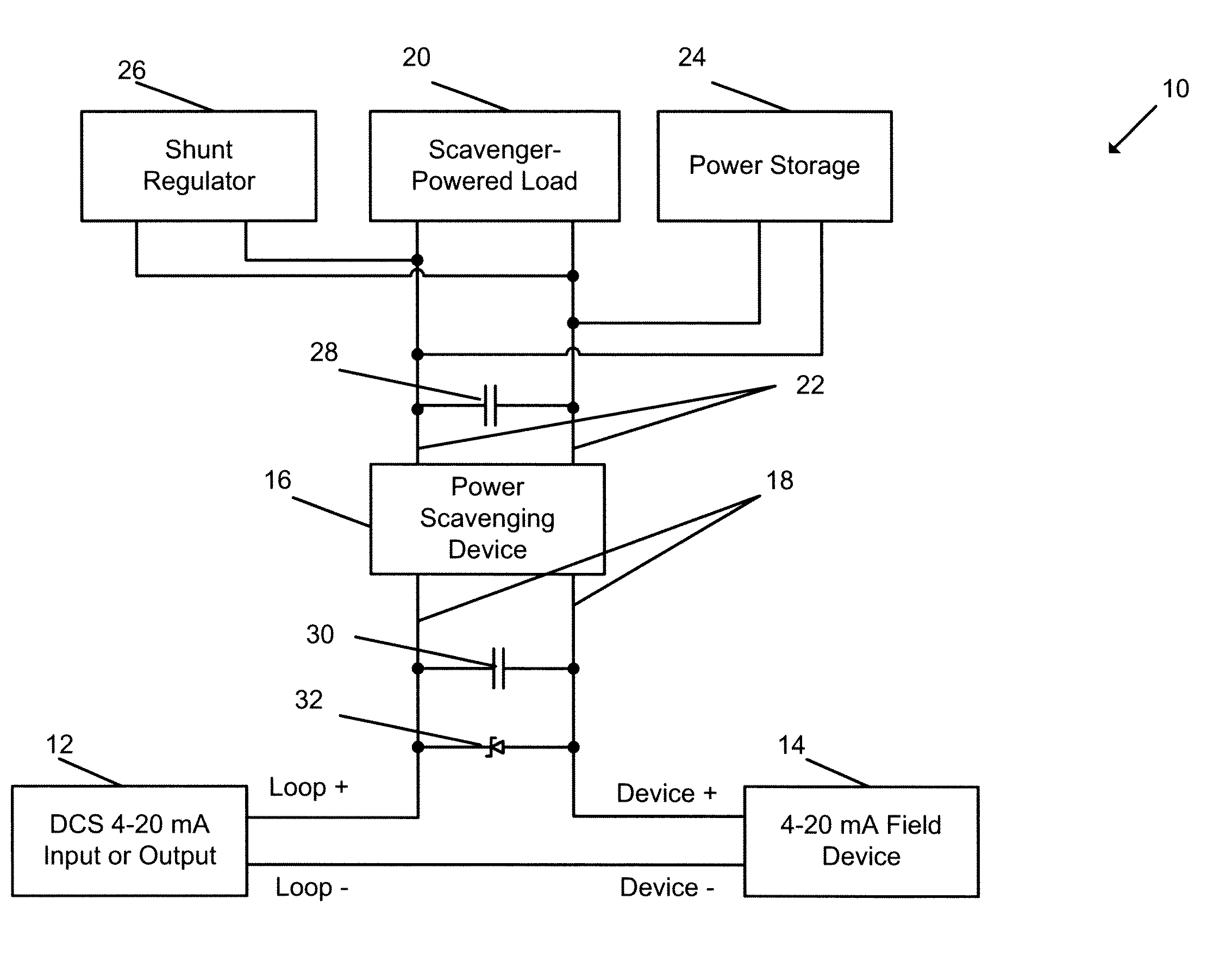
Figure 1 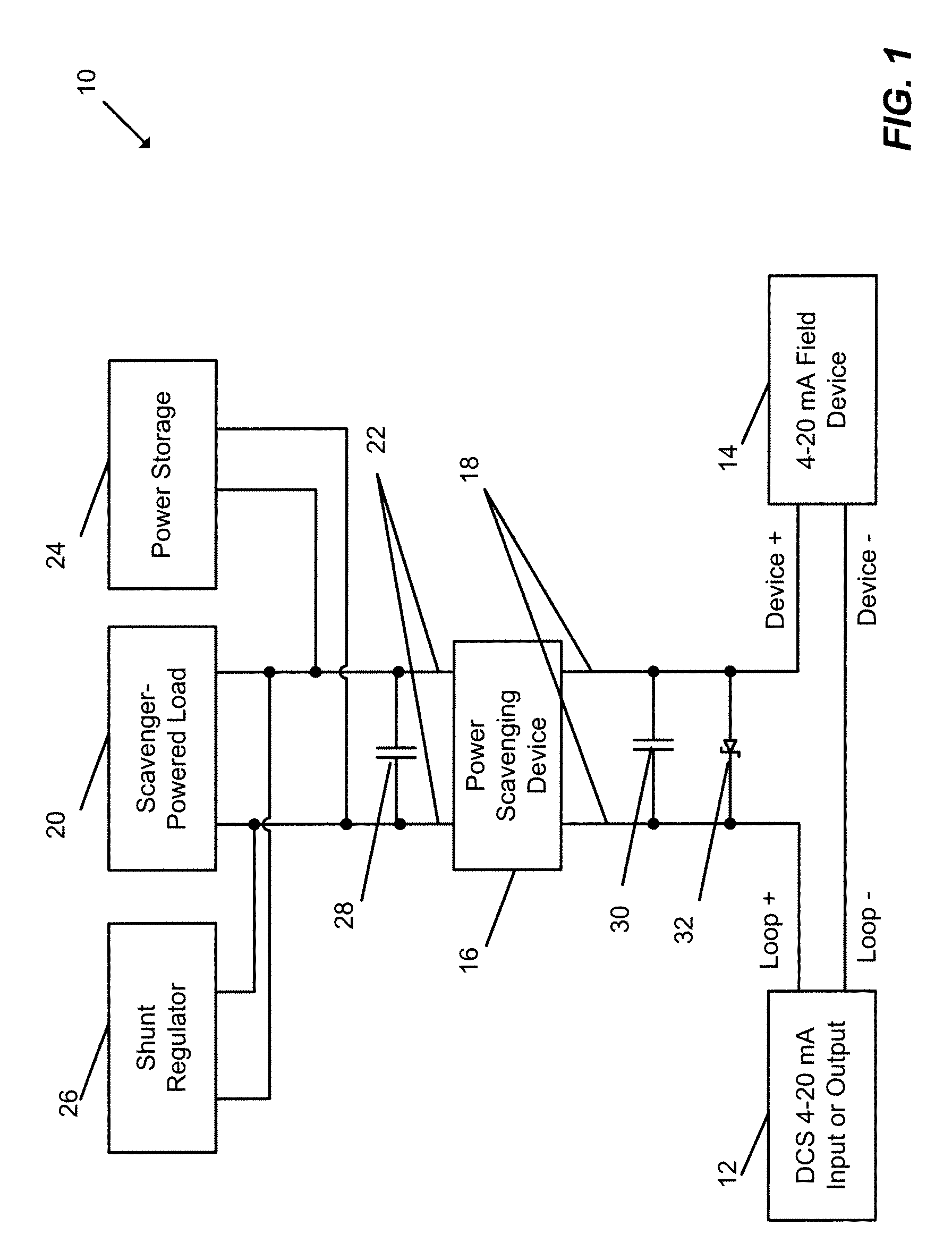
Figure 2 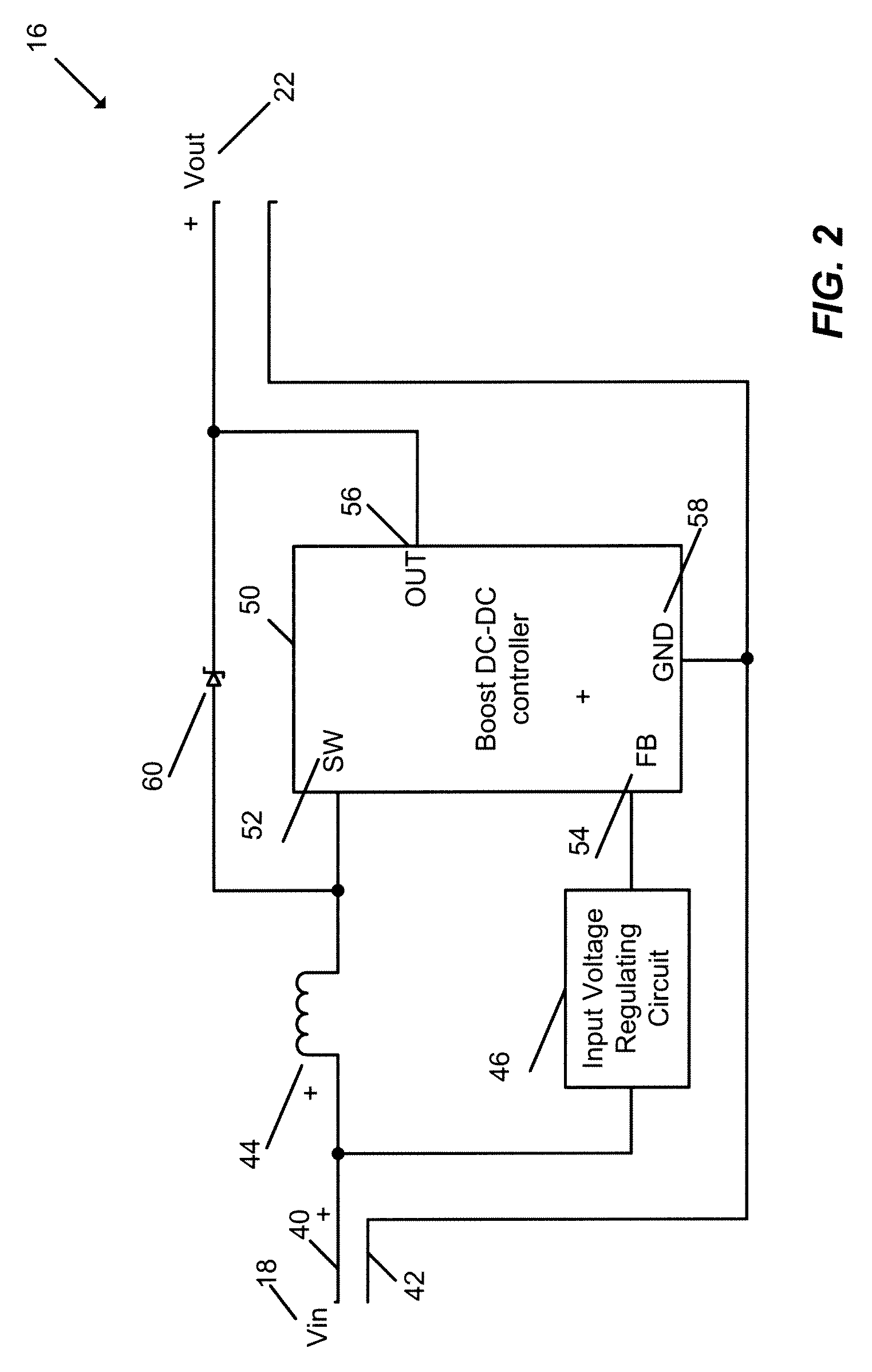
Figure 3
Abstract
Description
CROSS-REFERENCE TO RELATED APPLICATIONS
[0001] This application claims benefit of the following U.S. Provisional Application Ser. No. 60 / 944,454, entitled “Input Regulated DC to DC Converter for Power Scavenging” filed Jun. 15, 2007, the disclosure of which is hereby expressly incorporated herein by reference.FIELD OF THE INVENTION
[0002] The present invention relates generally to voltage and power conversion circuits and, more particularly, to a method and apparatus for regulating input voltage of a DC to DC converter.DESCRIPTION OF THE RELATED ART
[0003] DC to DC converters are used in a variety of applications to produce regulated voltage. Some converters, known as step-up or boost converters, generate higher voltage at the output terminals than is available at the input terminals. Conversely, step-down converters generate lower voltage at the output terminals. The DC to DC converters known in the art typically operate by controlling, through dedicated switching circuitry, the timing a...
Examples
Embodiment Construction
[0020]FIG. 1 is a schematic representation of a system in which an input-regulated power scavenging device may be used to efficiently harvest excess power from a current loop and direct the excess power to a load, a storage device, or both. As illustrated in FIG. 1, a current loop or circuit 10 includes a Distributed Control System (DCS) 12, a field device 14, and a power scavenging device 16 connected in series with the field device 14. These and other circuit elements illustrated in FIG. 1 are connected in a wired manner.
[0021]In operation, the DCS 12 and the field device 14 send and receive 4-20 mA analog signals in a manner unpredictable to the scavenging device 16 implemented as an input regulated DC to DC converter. In other words, from the perspective of the scavenging device 16, the current in the loop 10 may uncontrollably vary with time in the 4 to 20 mA range. The power scavenging device is connected to the loop 10 in series through a pair of input terminals 18, with one ...