Intrinsic Safety Barrier

a safety barrier and output barrier technology, applied in emergency protective arrangement details, emergency protective arrangement for limiting excess voltage/current, electrical equipment, etc., can solve the problems of combustible gasses and/or dusts, flammable gases, vapors or dusts that are often accompanied by electrically-initiated explosions of flammable gas and dust, and the inability to produce a spark strong or hot enough, so as to improve the intrinsic safety barrier arrangement

Active Publication Date: 2016-08-25
MSA TECH
View PDF5 Cites 7 Cited by
  • Summary
  • Abstract
  • Description
  • Claims
  • Application Information

AI Technical Summary

Benefits of technology

[0011]Generally, provided is an improved intrinsic safety barrier arrangement for an electrical device or component. Preferably, provided is an improved intrinsic safety barrier that includes existing small printed circuit board components. Preferably, provided is an improved intrinsic safety barrier that includes low power / current rated discrete components. Preferably, provided is an improved intrinsic safety barrier that provides an intrinsically safe limited current. Preferably, provided is an improved intrinsic safety barrier that provides an intrinsically safe limited voltage. Preferably, provided is an improved intrinsic safety barrier that provides high voltage and high current isolation as required by intrinsic safety standards, but with small printed circuit board components.

Problems solved by technology

One type of hazardous location is where concentrations of flammable gases, vapors, or dusts occur.
The introduction of electrical apparatuses for signaling or lighting in coal mines was often accompanied by electrically-initiated explosions of flammable gas and dust.
One such method is designing electrical devices in a way so that they cannot produce a spark strong enough, or generate heat hot enough, to ignite combustible gasses and / or dusts.
In such apparatuses, insufficient energy is available under the most onerous fault conditions to produce an arc that can ignite the surrounding explosive atmosphere, and insufficient energy is available under the most onerous fault conditions to produce sufficient heat to ignite the surrounding explosive atmosphere.
Generated heat, under certain fault conditions, such as an internal short in a semiconductor device, becomes an issue as the temperature of a component can rise to a level that can ignite some explosive gases and dusts, even in normal use.
In many highly compact electrical devices used today, printed circuit boards often have component spacing that make it difficult to reduce the possibility of arcing between components, with or without dust or other particulate matter working onto the circuitry.

Method used


Image

  • Intrinsic Safety Barrier
  • Intrinsic Safety Barrier
  • Intrinsic Safety Barrier

Examples


Embodiment Construction

[0048]It is to be understood that the invention may assume various alternative variations and step sequences, except where expressly specified to the contrary. It is also to be understood that the specific devices and processes illustrated in the attached drawings, and described in the following specification, are simply exemplary embodiments of the invention. Hence, specific dimensions and other physical characteristics related to the embodiments disclosed herein are not to be considered as limiting. Certain preferred and non-limiting embodiments or aspects of the present invention will be described with reference to the accompanying figures.

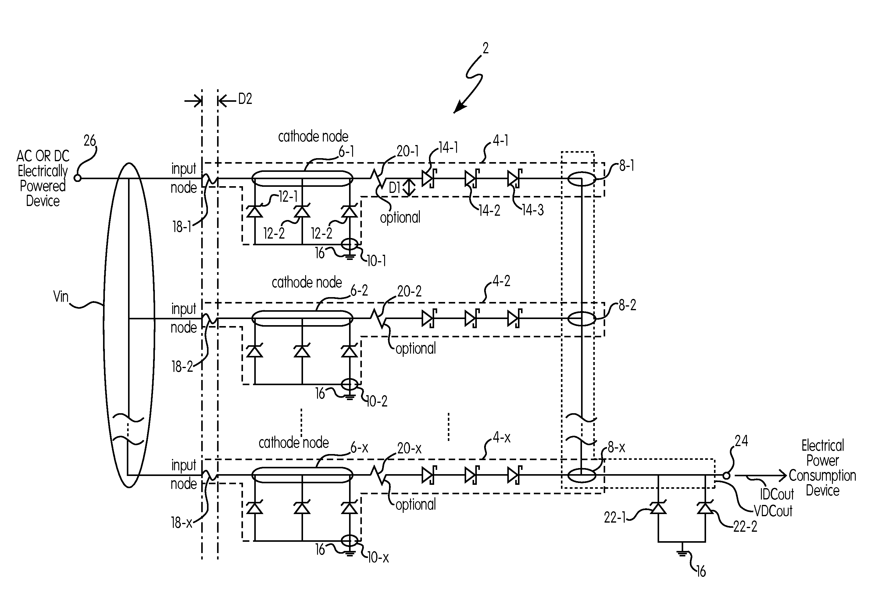
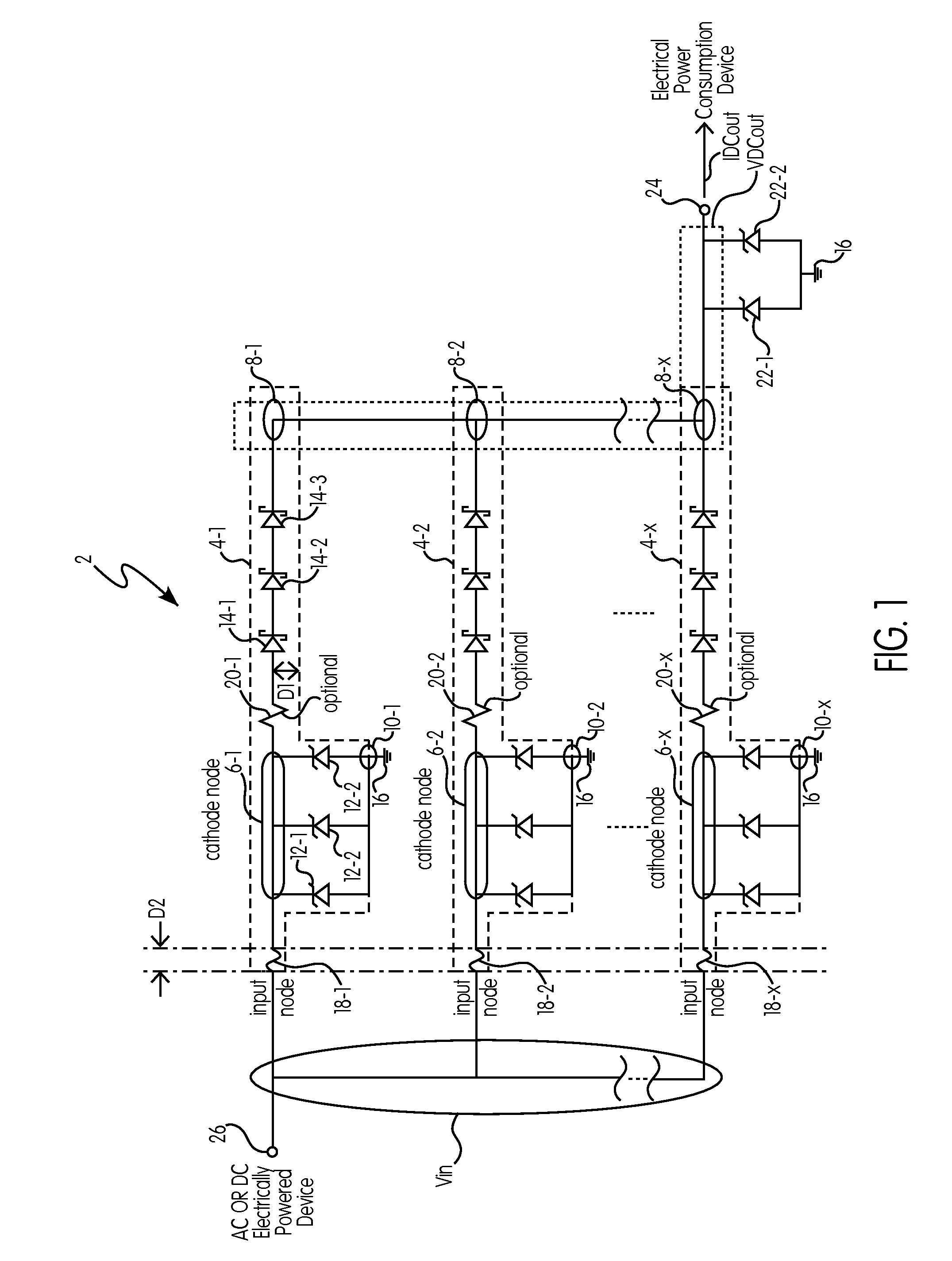
[0049]In one preferred and non-limiting embodiment or aspect, provided is an intrinsic safety barrier for conditioning electrical power provided from an AC or DC electrically powered device that is not configured to be intrinsically safe to a DC power consumption or DC powered device that is configured to be intrinsically safe. As used herein, ...


PUM


Abstract

An improved intrinsic safety barrier arrangement for an electrical device or component. A method of intrinsic safety barrier operation for an electrical device or component is also disclosed.

Description

BACKGROUND OF THE INVENTION[0001]1. Field of the Invention[0002]The present invention relates to intrinsically safe limited voltage and current output barriers, located in what is known in the industry as an associated apparatus, and which are required to be installed at each electrical interface between an intrinsically safe device and another circuit located within the associated apparatus not deemed intrinsically safe so that the protective components and construction is not damaged in the intrinsically safe device while connected to the associated apparatus having intrinsically safe limited voltage and current output provided by the barrier circuit.[0003]2. Description of the Related Art[0004]One type of hazardous location is where concentrations of flammable gases, vapors, or dusts occur. Electrical equipment installed in such locations must be specially designed and tested to ensure it does not initiate an explosion, due to arcing contacts or high surface temperature of equipm...

Claims


Application Information

Patent Timeline
Patent Type & Authority Applications(United States)
IPC IPC(8): H02H1/04H02H9/04
CPCH02H1/04H02H9/04H02H9/043H02H9/02H02H9/008
Inventor KANCEL, STEPHEN M.
Owner MSA TECH
Why Eureka
Try Eureka