
Printer

a printing machine and printing plate technology, applied in the field of printing machines, can solve the problems of insufficient inability to realize the above-described separation of sheet materials after a transfer process, and inability to achieve smooth and efficient transfer of print images, so as to prevent the lifting of print media and facilitate the effect of printing processing

Inactive Publication Date: 2011-03-22
TEAC CORP
View PDF10 Cites 0 Cited by
  • Summary
  • Abstract
  • Description
  • Claims
  • Application Information

AI Technical Summary

Benefits of technology

[0012]According to the present invention, the print medium is pushed down by the retaining member installed downstream from the separating position in the printing direction, to thereby prevent lifting of the print medium. Then, in this way, because the sheet member is always separated with reliability, print processing can be performed smoothly and efficiently.

Problems solved by technology

However, the clamping lugs effectively function only for optical discs having a center hole, while flat shaped print media having no center hole, such as magnetic cards or IC cards, are typically simply placed on the print tray in many cases.
However, for the print medium in which the center hole is not provided, the above-described separation of the sheet material subsequent to a transfer process could not be realized smoothly and efficiently in some cases.
Accordingly, there have been problems that the print image is not sufficiently transferred, and that failure is caused by taking up the sheet member with the print medium which remains affixed to the sheet member.

Method used


Image

  • Printer
  • Printer
  • Printer

Examples


Embodiment Construction

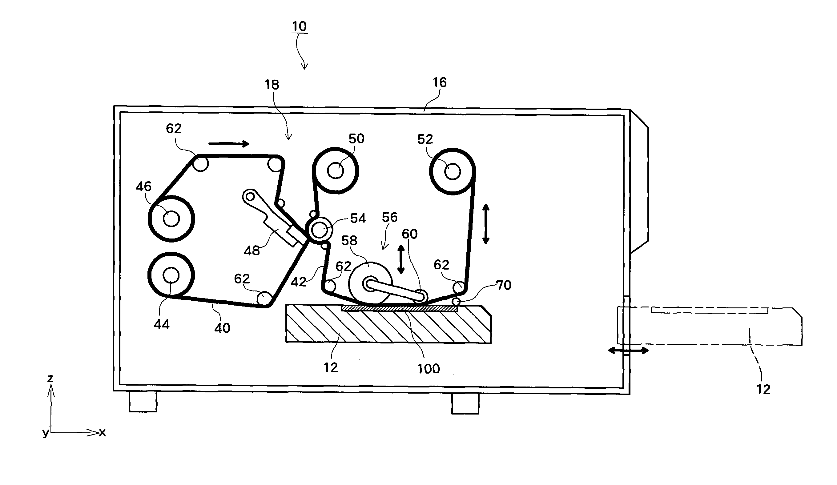
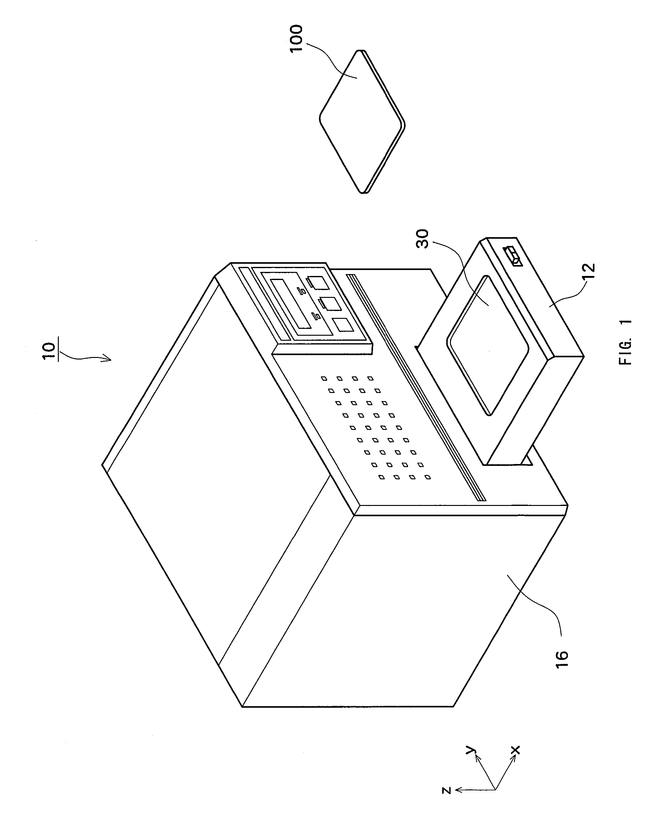
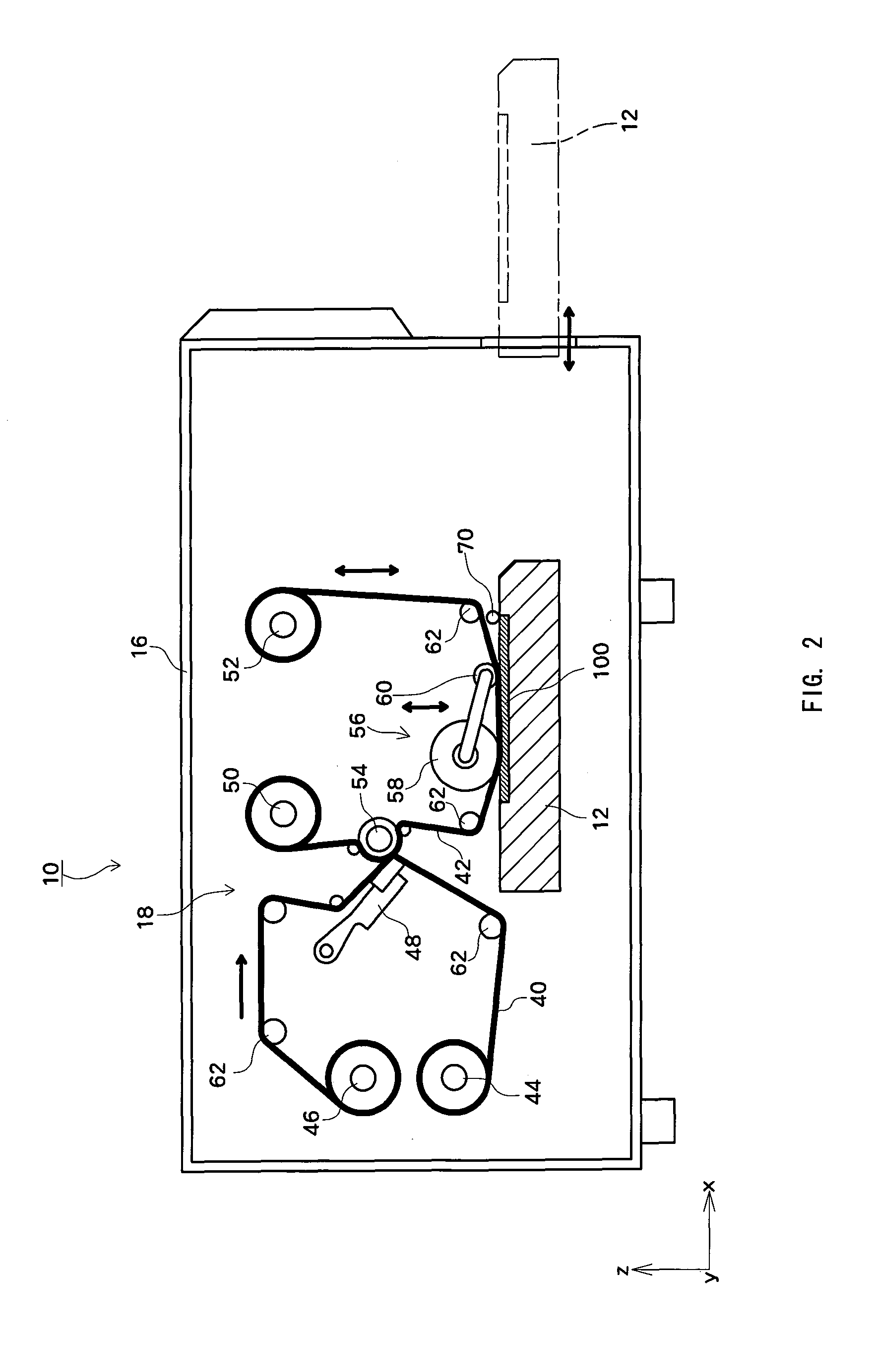
[0025]A preferred embodiment of the present invention will be described hereunder by reference to the drawings. FIG. 1 is a perspective view of a printer 10 according to the embodiment of this invention, and FIG. 2 shows a schematic configuration of the printer 10. The printer 10 is an apparatus for performing print processing of a print medium which is relatively thick and stiff, such as, for example, a magnetic card or an IC card.

[0026]A print medium 100 is transported while being supported by a print tray 12. The print tray 12 can advance and retreat along a direction (an X direction in FIGS. 1 and 2) substantially orthogonal to a rotation axis of a heat roller 58 which will be described below. Then, when the print tray 12 advances or retreats, the print medium 100 supported by the print tray 12 is transported to the outside or inside of a housing 16. A housing recess 30 is formed on an upper surface of the print tray 12 in which the print medium 100 is placed and housed in the h...


PUM


Abstract

A printer comprises a transfer assembly 56 for transferring a print image formed on an intermediate transfer sheet 42 to a print surface of a print medium 100, a print tray 12 on which the print medium 100 is placed, and a retaining roller 70 installed slightly downstream of the transfer assembly 56. The retaining roller 70 which is biased downward pushes the print medium 100 from above, to thereby prevent the print medium 100 from being lifted up.

Description

PRIORITY INFORMATION[0001]This application claims priority to Japanese Patent Application No. 2008-202248, filed on Aug. 5, 2008, which is incorporated herein by reference in its entirety.BACKGROUND[0002]1. Technical Field[0003]The present invention relates to a printer which performs image printing on a print surface of a flat shaped print medium by a thermal transfer method.[0004]2. Related Art[0005]Conventionally, printers for performing printing on print media which are stiff and shaped like plates, such as optical disks or magnetic cards, have been known (for example, refer to Japanese patent publication JP 2007-301879 A). In some such printers, the print medium is usually placed on a print tray and transported with the print tray. A recessed section which has a shape conforming to an outside shape of the print medium is formed on the print tray. Then, positioning of a recording medium relative to the print tray is achieved by placing and housing the print medium in the recesse...

Claims


Application Information

Patent Timeline
Patent Type & Authority Patents(United States)
IPC IPC(8): B41J3/407B41J2/325
CPCB41J2/0057B41J2/325
Inventor MIZUKAMI, JUNICHI
Owner TEAC CORP
Learn More