Fixing device having good warm-up property and image formation apparatus

a fixing device and warm-up property technology, which is applied in the direction of electrographic process, electric/magnetic/electromagnetic heating, instruments, etc., can solve the problems of inability to easily transmit heat, temperature of portions of heat generation members that do not, and recording sheets (hereinafter). , to achieve the effect of reducing the warm-up period, reducing the heat generation member's heat capacity, and saving energy and spa

Active Publication Date: 2011-03-22
KONICA MINOLTA BUSINESS TECH INC
View PDF17 Cites 8 Cited by
  • Summary
  • Abstract
  • Description
  • Claims
  • Application Information

AI Technical Summary

Benefits of technology

[0015]The present invention is conceived in view of the foregoing problems. An object of the present invention is to provide a fixing device that can control a temperature thereof with the use of a magnetic shunt alloy and making a heat capacity of the heat generation member smaller than that of the prior art so that the fixing device can save energy and have good warm-up property, and an image formation apparatus having the same fixing device.
[0018]Thus, since the conductive heat generation layer, the magnetic shunt alloy layer, and the low resistance conductive layer are integrally layered, the components present inside of the closed rotation path of the fixing belt can be downsized and accordingly the fixing belt can be shortened. Thus, the present invention can control its own temperature with the use of the magnetic shunt alloy, and in addition, can have the lower heat capacity of the fixing belt than the prior art, thereby saving energy and having the good warm-up property.
[0019]Heat is generated in the magnetic shunt alloy layer as well. However, if the conductive heat generation layer as in the present invention is absent and if the magnetic shunt alloy layer is made to generate heat, instead, for example, note that it is difficult for the magnetic shut alloy layer to generate an amount of heat necessary for the fixing device. As a result, the warm-up property is poor so that the warm-up period cannot be reduced. In addition, increasing the power output of the excitation coil contradicts the energy saving. According to the present invention, since the conductive heat generation layer is provided above the magnetic shut alloy layer, heat generation efficiency is improved so that energy can be saved and the good warm-up property can be obtained.
[0023]Thus, since the conductive layer is absent in the area corresponding to a portion of the fixed plate with which a recording sheet of all serviceable sizes is in contact, the heat capacity of the heat generation member can be reduced. Accordingly, more energy can be saved and a good warm-up property can be obtained.
[0030]Thus, since the friction caused by the slide between the fixed belt and the fixed plate is reduced, driving torque of the fixing belt is reduced. Consequently, energy can be saved and the durability thereof can be improved.
[0032]Thus, according to the present invention, the belt is much shorter than each disclosure of Patent Document 1 or 2 having two rollers inside the inner circumference of the belt. Consequently, according to the present invention, the heat capacity of the heat generation member is small, which is very advantageous in terms of energy and space saving, reduction of warm-up period and the like.

Problems solved by technology

However, with the heat generation member having a small heat capacity, the heat cannot be easily transmitted.
Here, if small-sized recording sheets having a small width are continuously used, the temperature of portions of the heat generation member that do not come into contact with the recording sheets (hereinafter, “contactless portions”) will be abnormally increased, the contactless portions being outer edges of the heat generation member in the width direction thereof.
This may thermally damage or deteriorate the components positioned in the vicinity of the contactless portions.
Also, if a recording sheet having a large width is used immediately after the small-sized recording sheets, then the hot offset will occur only in the outer edges of the printed sheet in the width direction thereof, and the printed recording sheet will have uneven glossiness.
According to Patent Document 1, the fixing belt has a very small heat capacity, rendering a warm-up period extremely short.
This is not suitable for saving energy.
Furthermore, if the fixer has a poor warm-up property, the user has to wait for quite a while upon turning on the power of the image formation apparatus, which is not favorable.

Method used


Image

  • Fixing device having good warm-up property and image formation apparatus
  • Fixing device having good warm-up property and image formation apparatus
  • Fixing device having good warm-up property and image formation apparatus

Examples


embodiment 1

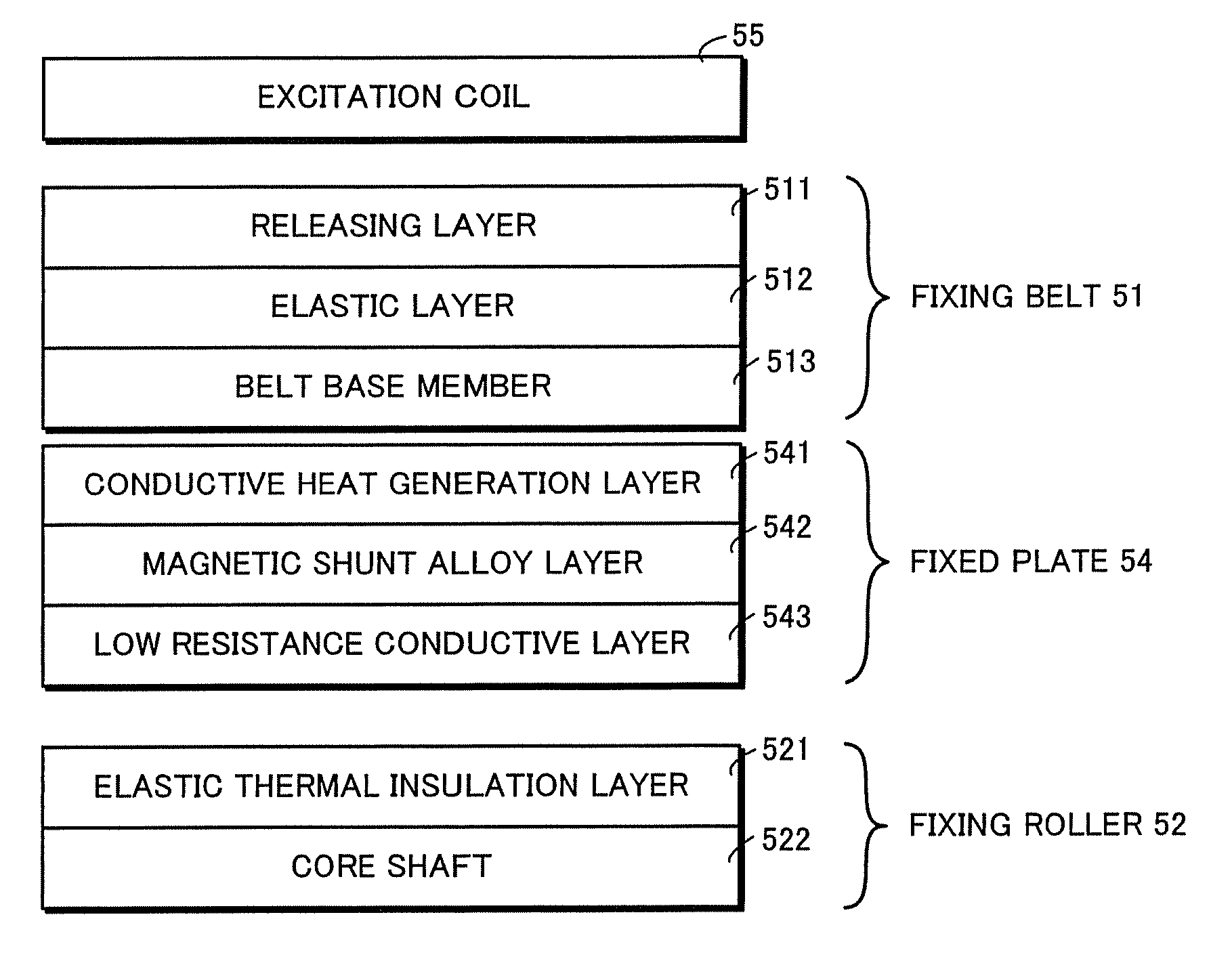
[0043]Embodiment 1 relates to an image formation apparatus having a fixing device that thermally fixes an unfixed image onto a recording sheet with the use of a heat source of an induction heating type. The image formation apparatus includes a fixed plate having a layer structure of a conductive heat generation layer, a magnetic shunt alloy layer and a low resistance conductivity layer that are integrally layered, positioned inside an inner circumference of the fixing belt, and opposed to an excitation coil. According to this embodiment, by appropriately setting a thickness of each layer, the fixing device has the self-temperature control function and reduces a heat capacity of a heat generation member such that the energy can be saved and the good warm-up property can be obtained.

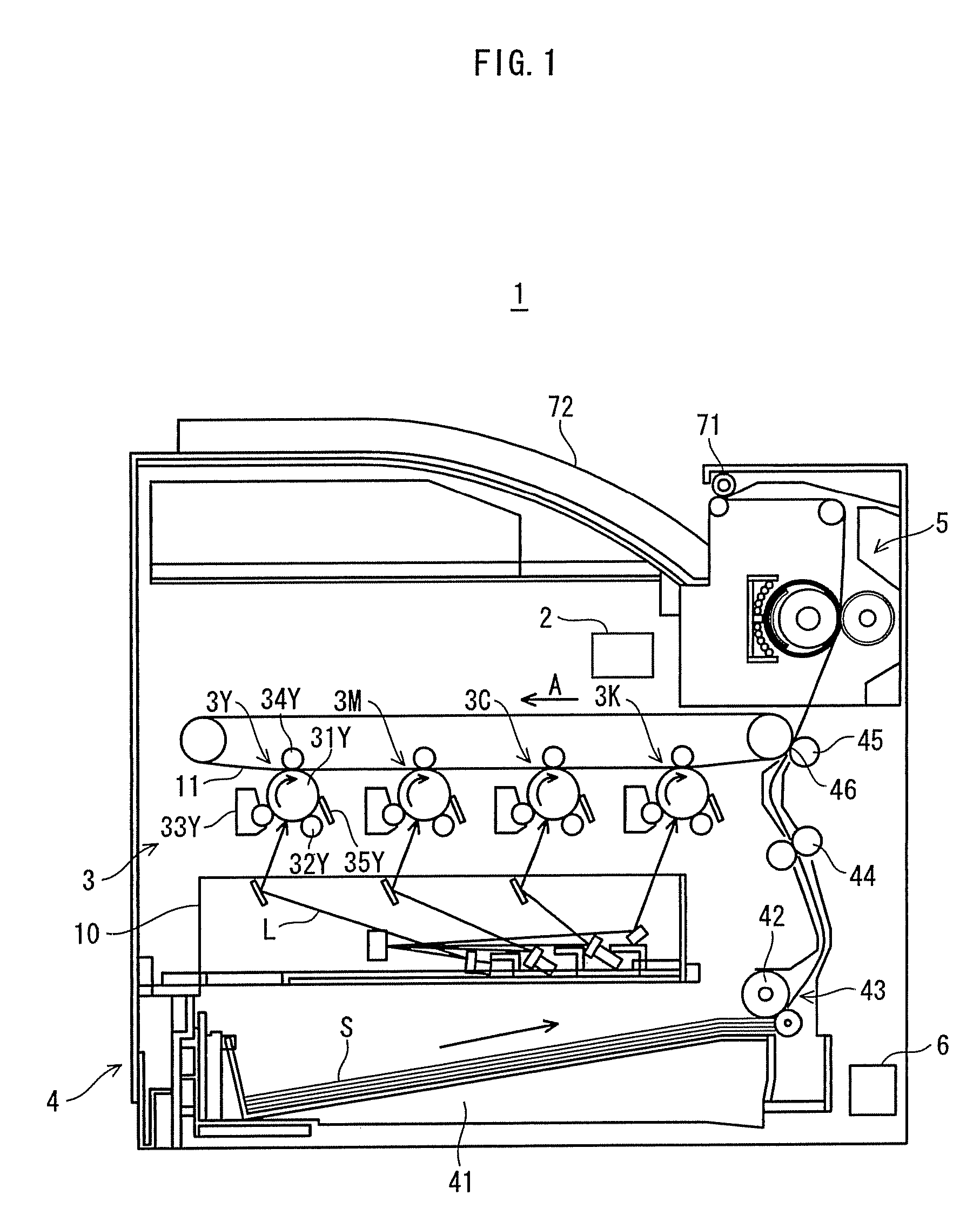
[0044]FIG. 1 shows an overall structure of an image formation apparatus according to this embodiment of the present invention.

[0045]As shown in FIG. 1, an image formation apparatus 1 of the present embodim...

modification 1

[Modification 1]

[0095]Modification 1 is different from Embodiment 1 only in part of the fixed plate. In the fixed plate according to Modification 1, the low resistance conductive layer is provided in the area of the fixed plate corresponding to the contactless portion with which a smallest-width recording sheet is out of contact when the sheet passes through the fixing nip. However, the low resistance conductive layer is absent in another area of the fixed plate corresponding to the contacting portion with which the smallest-width recording sheet is in contact when the sheet passes through the fixing nip. Thus, the fixing device of Modification 1 has the self-temperature control function and reduces a heat capacity of the heat generation member.

[0096]This modification is similar to Embodiment 1 except that the fixed plate 54 is replaced by the fixed plate 56.

[0097]Note that components of Modification 1 that are identical with those of Embodiment 1 have the same reference number as E...

modification 2

[Modification 2]

[0104]Modification 2 is different from Embodiment 1 only in part of the fixed plate. According to Modification 2, the fixed plate includes the low friction layer layered on a surface thereof that is frictionally in contact with the fixing belt.

[0105]FIG. 6 is a schematic view of a layer structure including the fixing roller 52, the fixed plate 57, the fixing belt 51 and the excitation coil 55 according to Modification 2.

[0106]Note that, components of Modification 2 that are identical with those of Embodiment 1 have identical reference numbers, and that explanations thereof are omitted.

[0107]In the layer structure shown in FIG. 6, the fixed plate 54 in the layer structure shown in FIG. 3 of Embodiment 1 is replaced by the fixed plate 57. Other than that, the layer structure of Modification 2 is similar to that of Embodiment 1.

[0108]The fixed plate 57 has the low friction layer 571, the conductive heat generation layer 541, the magnetic shunt alloy layer 542, and the l...


PUM


Abstract

Disclosed is a fixing device having a self-temperature control function, and reducing a heat capacity of a heat generation member for saving energy and achieving good warm-up property. The fixing device includes a fixed plate inside a closed rotation path of a belt, contacting an inner circumferential surface of the belt, substantially opposed to an excitation coil with the belt therebetween, keeping the belt on the rotation path. The fixed plate includes: a magnetic shunt alloy layer made of a magnetic shunt alloy; a conductive heat generation layer being disposed toward a main surface of the magnetic shunt alloy layer facing the belt, being made of a conductor other than the alloy, and being thinner than the alloy layer; and a low resistance conductive layer being disposed toward another main surface, having a lower electric resistance value than the heat generation layer, and being thicker than the heat generation layer.

Description

[0001]This application is based on application No. 2008-160576 filed in Japan, the contents of which are hereby incorporated by reference.BACKGROUND OF THE INVENTION[0002](1) Field of the Invention[0003]The present invention relates to an image formation apparatus including a fixing device, and in particular to technology for, when an image is thermally fixed on a smaller-sized recording sheet among several-sized recording sheets by using an induction heating method, suppressing a temperature increase in an area corresponding to a portion that is out of contact with the sheet when the sheet passes through a fixing nip thereof.[0004](2) Description of the Related Art[0005]In recent years, some fixing devices included in electrophotographic type image formation apparatuses or electrostatic recording type image formation apparatuses are starting to utilize heat sources of an induction heating type that are compact and have relatively high heat conversion efficiency. Such fixing devices...

Claims


Application Information

Patent Timeline
Patent Type & Authority Patents(United States)
IPC IPC(8): G03G15/20
CPCG03G15/2057G03G15/2064G03G2215/2029
Inventor MURAKAMI, MASANORI
Owner KONICA MINOLTA BUSINESS TECH INC
Why Eureka
Try Eureka