
Inhalation device for producing a drug aerosol

a technology of aerosol and inhalation device, which is applied in the direction of combustion type, respirator, burner, etc., can solve the problems of poor penetration and deposition of particles, poor particle size, and range between 10-100 nm and 1-3.5 m, and achieve the effect of reducing airflow

Inactive Publication Date: 2011-03-29
ALEXZA PHARMA INC
View PDF670 Cites 186 Cited by
  • Summary
  • Abstract
  • Description
  • Claims
  • Application Information

AI Technical Summary

Benefits of technology

[0014]The device may also include a bypass valve communicating with the chamber downstream of the unit for offsetting the decrease in airflow produced by the gas-flow control valve, as the user draws air into the chamber.

Problems solved by technology

Particle sizes that fall in the range between 10-100 nm and 1-3.5 μm tend to have poor penetration and poor deposition.

Method used


Image

  • Inhalation device for producing a drug aerosol
  • Inhalation device for producing a drug aerosol
  • Inhalation device for producing a drug aerosol

Examples


Embodiment Construction

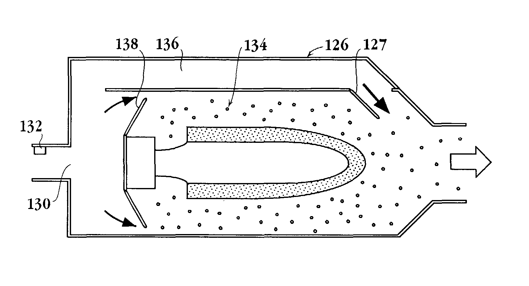
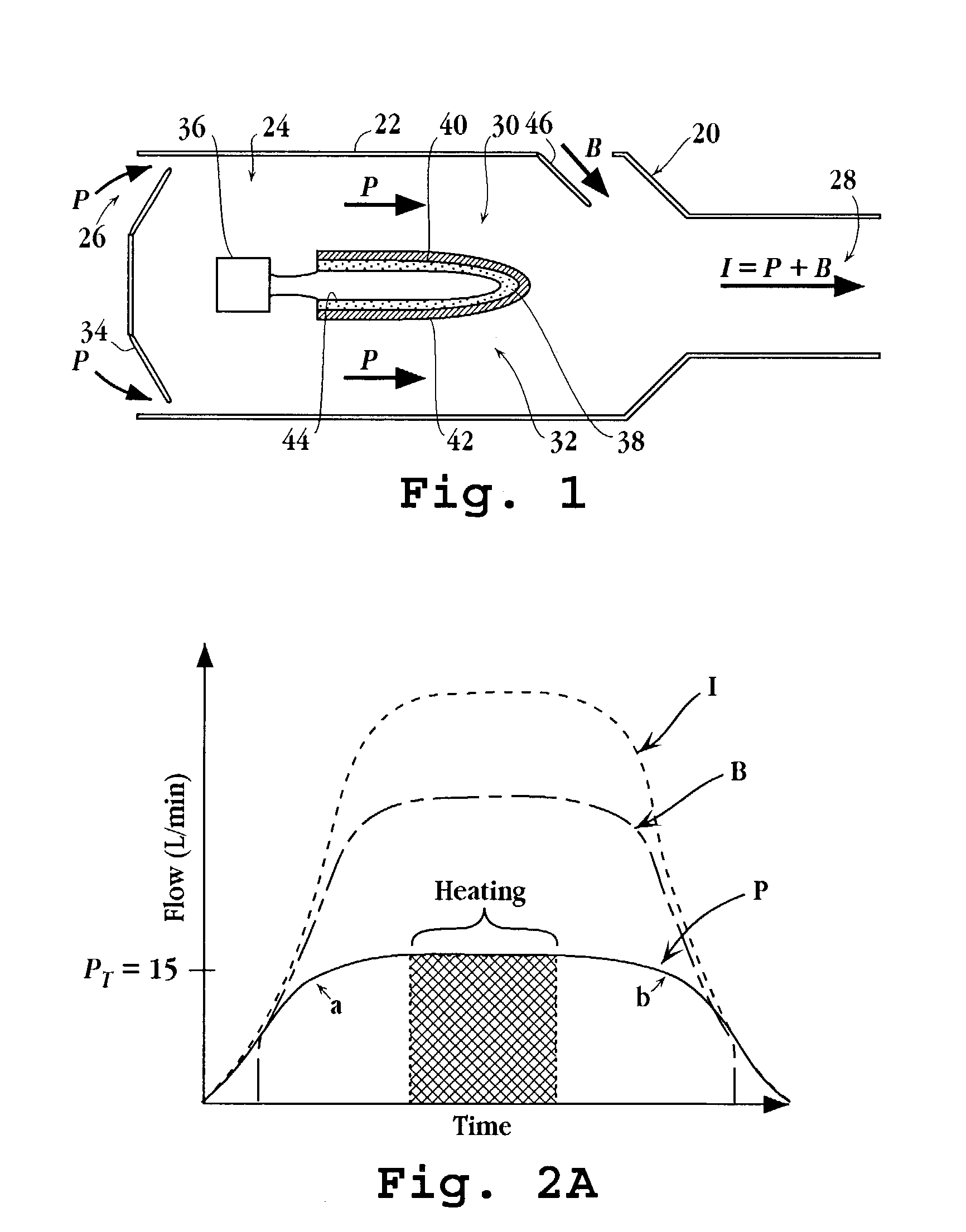
[0028]FIG. 1 is a simplified cross-sectional view of an inhalation device 20 for delivering a drug by inhalation. The device includes a body 22 defining an interior flow-through chamber 24 having upstream and downstream chamber openings 26, 28, respectively. A drug-supply unit 30 contained within the chamber is operable, upon actuation, to produce a heated drug vapor in a condensation region 32 of the chamber adjacent the substrate and between the upstream and downstream chamber openings. As will be detailed below, when gas is flowed across the surface of the drug-supply unit, with either laminar flow or with turbulence, at a selected velocity, the drug vapor condenses to form drug condensation particles having a selected MMAD particle size. As one of skill in the art would appreciate, the gas velocity through the chamber may be controlled by changing the volumetric gas-flow rate, cross-sectional area within the chamber, and / or the presence or absence of structures that produce turb...


PUM


Abstract

A device for delivering a drug by inhalation is disclosed. The device includes a body defining an interior flow-through chamber having upstream and downstream chamber openings, and a drug supply unit contained within the chamber for producing, upon actuation, a heated drug vapor in a condensation region of the chamber. Gas drawn through the chamber region at a selected gas-flow rate is effective to form drug condensation particles from the drug vapor having a selected MMAD between 0.02 and 0.1 MMAD or between 1 and 3.5 μm. A gas-flow control valve disposed upstream of the unit functions to limit gas-flow rate through the condensation region to the selected gas-flow rate. An actuation switch in the device activates the drug-supply unit, such that the drug-supply unit can be controlled to produce vapor when the gas-flow rate through the chamber is at the selected flow rate.

Description

[0001]This application claims the benefit of U.S. provisional application Ser. No. 60 / 429,776 filed Nov. 27, 2002, for “Method and Apparatus for Controlling Flow of Gas over a Composition,” and U.S. provisional application Ser. No. 60 / 429,586, filed Nov. 27, 2002 for “Flow-Actuated Medical Device.” Both of these applications are incorporated herein by reference in their entirety.FIELD OF THE INVENTION[0002]The present invention relates to an inhalation device for producing desired-size drug-aerosol particles for inhalation.BACKGROUND OF THE INVENTION[0003]Therapeutic compounds may be administered by a variety of routes, depending on the nature of the drug, the pharmacokinetic profile desired, patient convenience, and cost, among other factors. Among the most common routes of drug delivery are oral, intravenous (IV), intramuscular (IM) intraperitoneal (IP) subcutaneous, transdermal, transmucosal, and by inhalation to the patient's respiratory tract.[0004]The inhalation route of drug ...

Claims


Application Information

Patent Timeline
Patent Type & Authority Patents(United States)
IPC IPC(8): A61M15/08F23D11/00F23D14/00A61M11/00A61M11/04A61M15/00
CPCA61M11/041A61M15/00A61M11/002A61M11/042A61M11/047
Inventor CROSS, STEPHENHODGES, CRAIG C.HALE, RON L.LLOYD, PETER M.MYERS, DANIEL J.QUINTANA, REYNALDO J.RABINOWITZ, JOSHUA D.TOM, CURTISWENSLEY, MARTIN J.
Owner ALEXZA PHARMA INC
Learn More