Probe connector

a technology of probe connectors and connectors, which is applied in the direction of coupling contact members, coupling device connections, electrical apparatus, etc., can solve the problems of reducing the use lifetime of electrical devices, and achieve the effects of prolonging the use lifetime of probe connectors, reducing heat generation, and simplifying the assembling process

Inactive Publication Date: 2011-03-29
CHENG UEI PRECISION IND CO LTD
View PDF4 Cites 35 Cited by
  • Summary
  • Abstract
  • Description
  • Claims
  • Application Information

AI Technical Summary

Benefits of technology

[0007]As described above, the probe connector is provided with the conduct element which is extended from the barrel and soldered to the PCB to connect the barrel and the PCB electrically and directly, which not only decreases the heat generation, prolonging the use lifetime of the probe connector, but also simplifies the assembling process, guaranteeing the stable transmission of the electrical signals. In addition, the barrel has the notch engaged with the mating lump, which is excellent to position the barrel in the inserting hole, improving the connection stability of the probe connector.

Problems solved by technology

However, since the conduct element 503 is manufactured and used to connect the probe pin assembly 502 and the PCB electrically, as a conductor, it is possible to aggravate the heat generation of an electrical device which is equipped with the probe connector 5 in work, because of the large resistivity of the conduct element 503, as a result, which decreases the use lifetime of the electrical device.

Method used


Image

  • Probe connector
  • Probe connector
  • Probe connector

Examples


Embodiment Construction

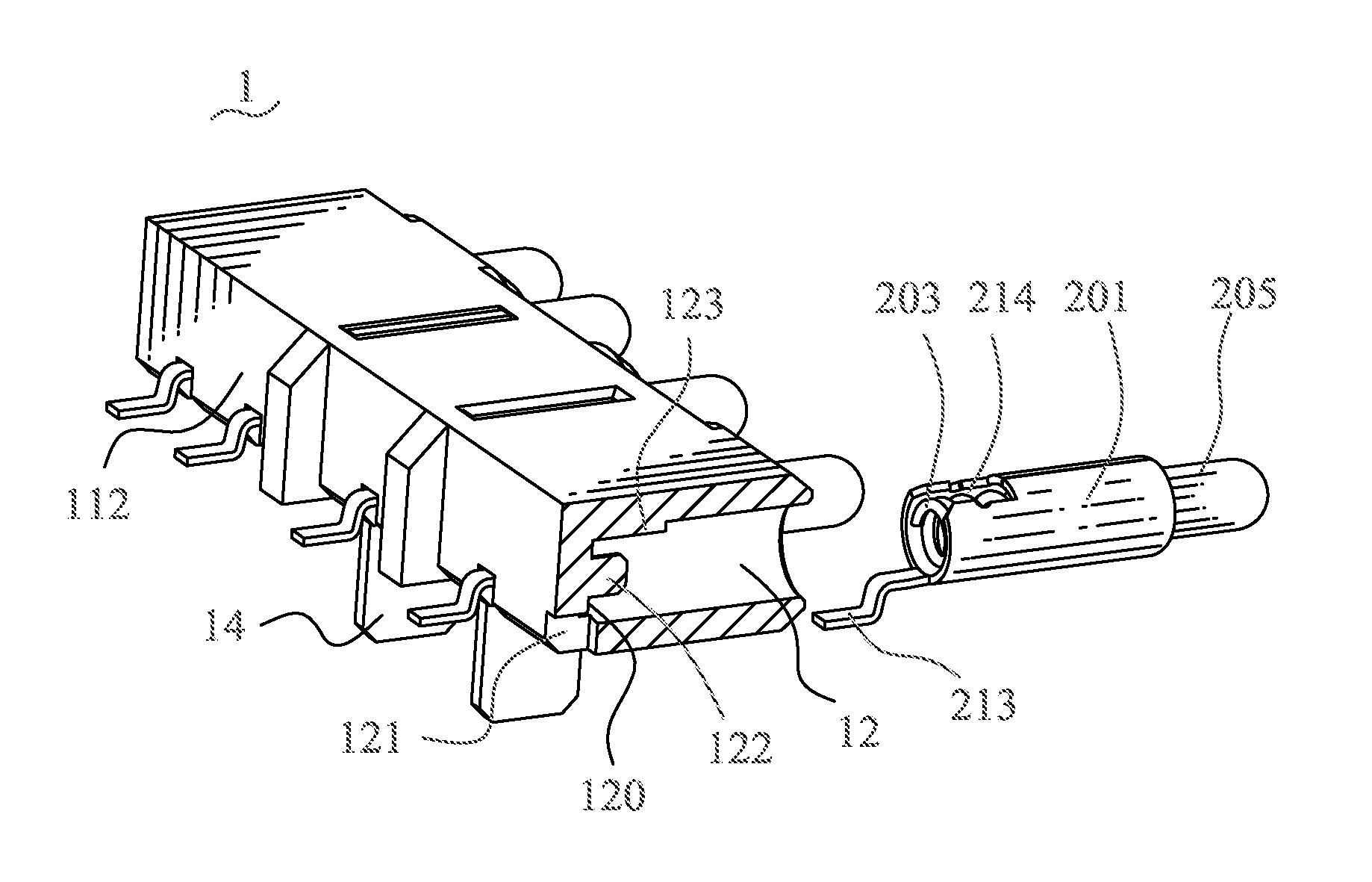
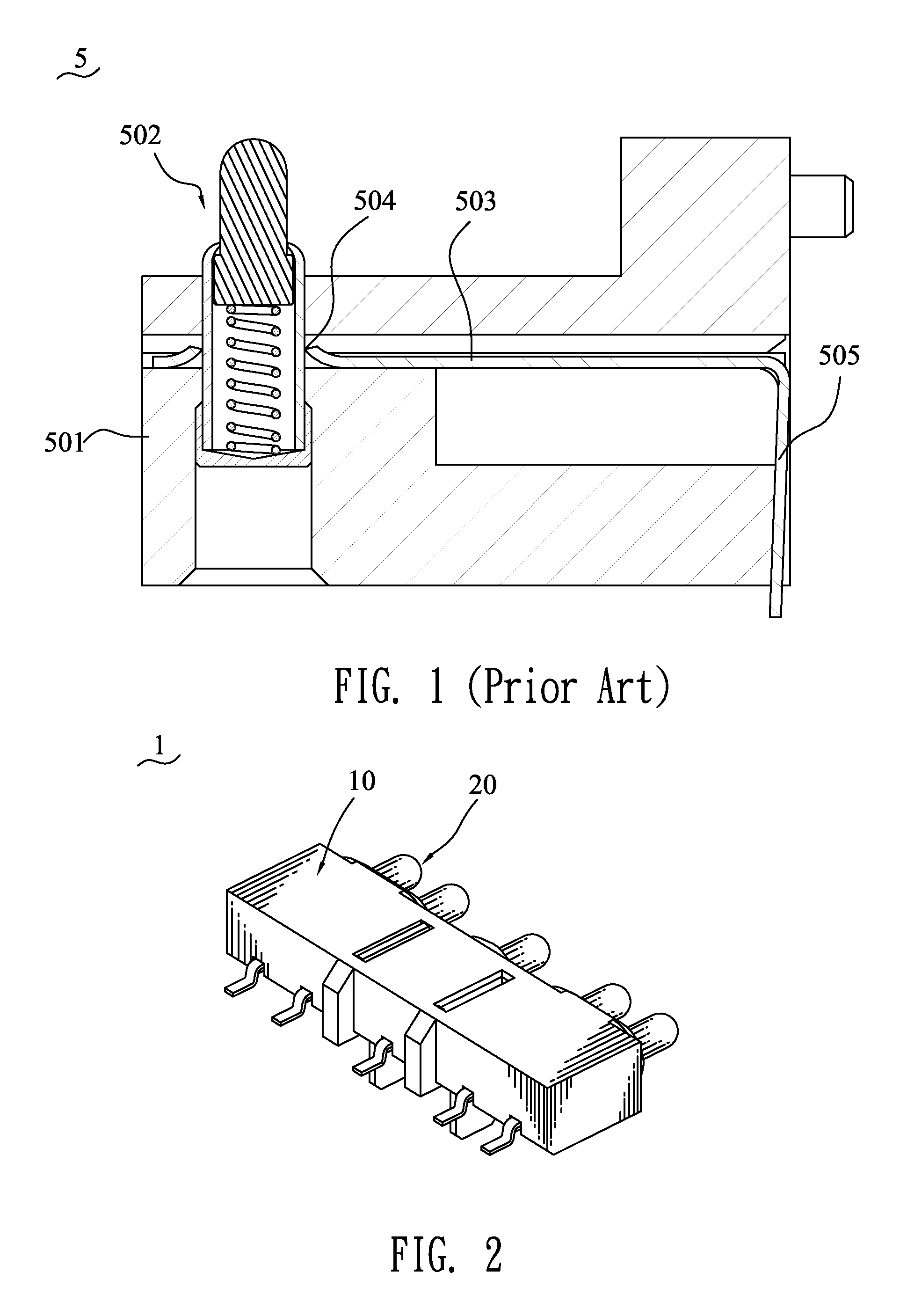
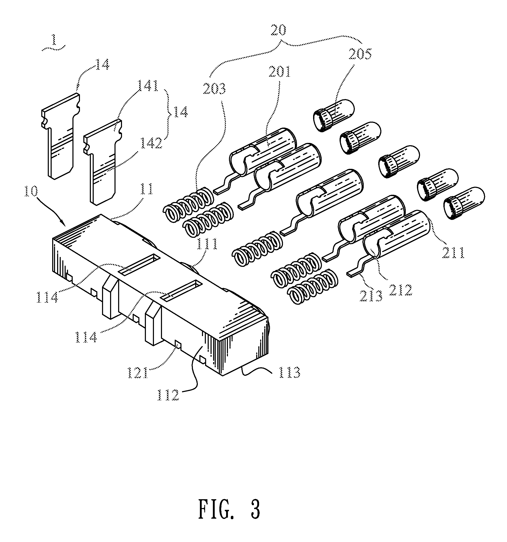
[0016]Referring to the drawings in greater detail, and first to FIGS. 2-4, the embodiment of the present invention is embodied in a probe connector 1. The probe connector 1 includes an insulating housing 10, a plurality of probe pin assemblies 20 mounted to the insulating housing 10. The insulating housing 10 has a substantially rectangular base 11. The base 11 defines a front surface 111, a rear surface 112, and a bottom surface 113 connecting with the front surface 111 and the rear surface 112. The front surface 111 has a plurality of columned inserting holes 12 for receiving the probe pin assemblies 20. The inserting holes 12 are arranged side by side and extend rearward a predetermined distance, with closed rear ends formed thereof. In this embodiment, there are five inserting holes. Each of the inserting holes 12 has a channel 121 at a bottom 120 thereof and reaching the rear surface 112. In this embodiment, the bottom 120 of the inserting hole 12 is further protruded frontward...


PUM


Abstract

A probe connector includes an insulating housing having a base, and a plurality of probe pin assemblies. The base defines a front surface which has a plurality of inserting holes arranged side by side. The inserting hole has a channel at a bottom thereof and reaching a rear surface of the base, and a mating lump protruded inwards from a rear portion of an inner surface thereof. The probe pin assembly has a cylindraceous barrel received in the inserting hole, an elastic element accommodated in the barrel, and a plunger. The barrel has a notch at a rear end of a periphery thereof for engaging with the mating lump. A conduct element of strip shape is extended rearwards from the rear end of the barrel, and exposed out of the insulating housing through the channel for being soldered to a PCB.

Description

BACKGROUND OF THE INVENTION[0001]1. Field of the Invention[0002]The present invention relates to a probe connector, and particularly to a probe connector connected to a PCB.[0003]2. The Related Art[0004]Please refer to FIG. 1, a conventional probe connector 5 for transmitting electrical signals is generally involved with an insulating housing 501, a probe pin assembly 502 mounted in the insulating housing 501, and a conduct element 503. The conduct element 503 is substantially L-shaped. One free end of the conduct element 503 is formed with a positioning hole 504. The probe pin assembly 502 is restrained in the positioning hole 504 for fixing the probe pin assembly 502 to the insulating housing 501. The other free end of the conduct element 503 is defined as a soldering end 505, which extends out of the insulating housing 501 for being soldered to a printed circuit board (PCB, not shown). Therefore, the probe pin assembly 502 is electrically connected with the PCB by means of the co...

Claims


Application Information

Patent Timeline
Patent Type & Authority Patents(United States)
IPC IPC(8): H01R13/24
CPCH01R12/57H01R12/724H01R13/2421
Inventor LIN, MING-HAN
Owner CHENG UEI PRECISION IND CO LTD
Why Eureka
Try Eureka