Oil-free chain

a technology of oil-free chain and oil-free, which is applied in the direction of driving chains, belts/chains/gearrings, chain elements, etc., can solve the problems of increasing the cost of chain manufacturing, increasing the number of chain parts, and increasing the difficulty of chain assembly and cost, so as to avoid the reduction in the strength of outer plates, reduce the module of outer plates, and simplify production.

Inactive Publication Date: 2011-03-29
TSUBAKIMOTO CHAIN CO
View PDF20 Cites 8 Cited by
  • Summary
  • Abstract
  • Description
  • Claims
  • Application Information

AI Technical Summary

Benefits of technology

[0014]The protrusion of the bushings into recesses in the outer plates forms a labyrinth structure which exhibits an oil-retention function, so that the leakage of lubricating oil from the space between the bushing and the connecting pin due to inertial force generated by circulating travel of the chain is suppressed. The labyrinth structure also suppresses invasion of the dust into the space between the bushing and the connecting pin. Thus, wear of the inner circumferential surface of the bushing and the outer circumferential surface of the connecting pin is reduced, and wear elongation of the chain can be prevented for a long period of time.
[0021]When the bulged portion opposite the bushing-receiving recess has an outer diameter larger than the diameter of the bushing-receiving recess, the modulus of the stepped portion of the outer plate can be at least as great, and even greater than, the modulus of the other parts of the outer plate. Thus, weakening of the plate and fatigue failure can be avoided. Similarly, when the bulged portion opposite the roller-receiving recess of the inner plate has an outer diameter larger than the diameter of the roller-receiving recess, the modulus of the stepped portion of the inner plate can be at least as great, and even greater than, the modulus of the other parts of the inner plate, and weakening of the inner plate and fatigue failure can be avoided.

Problems solved by technology

However, surface finishing requires additional manufacturing steps that increase the cost of manufacture of the chain.
In addition, since rigid rings are provided in addition to the elastic sealing rings, the number of chain parts is increased and assembly of the chain becomes more difficult and costly.
Here again, the problem of resistance to relative rotation can be addressed by surface finishing of the seal plates, the inside surfaces of the inner link plates, and the end surfaces of the rollers, but the surface finishing steps increase the cost and difficulty of manufacture.
Moreover the provision of the seal plate and the sealing ring increases the number of parts, also making assembly difficult and increasing manufacturing cost.

Method used


Image

  • Oil-free chain
  • Oil-free chain
  • Oil-free chain

Examples


Embodiment Construction

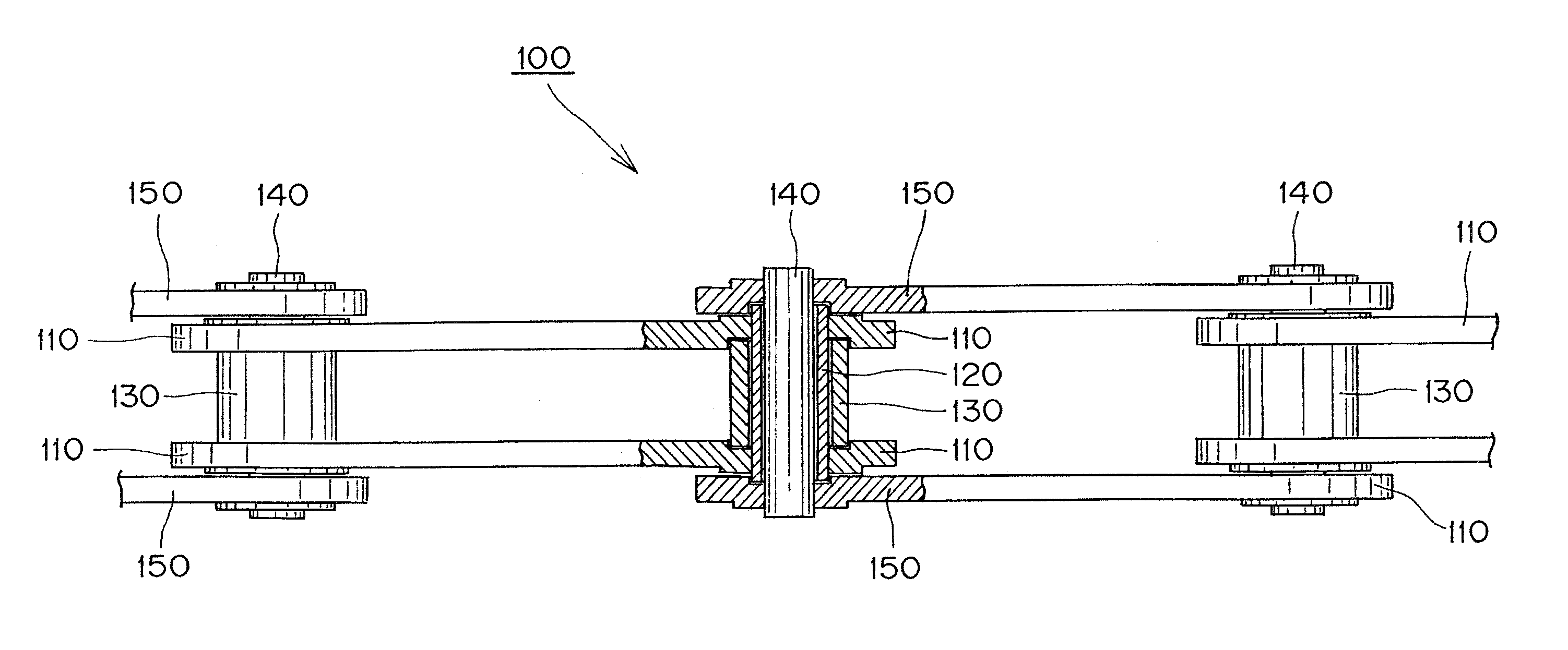
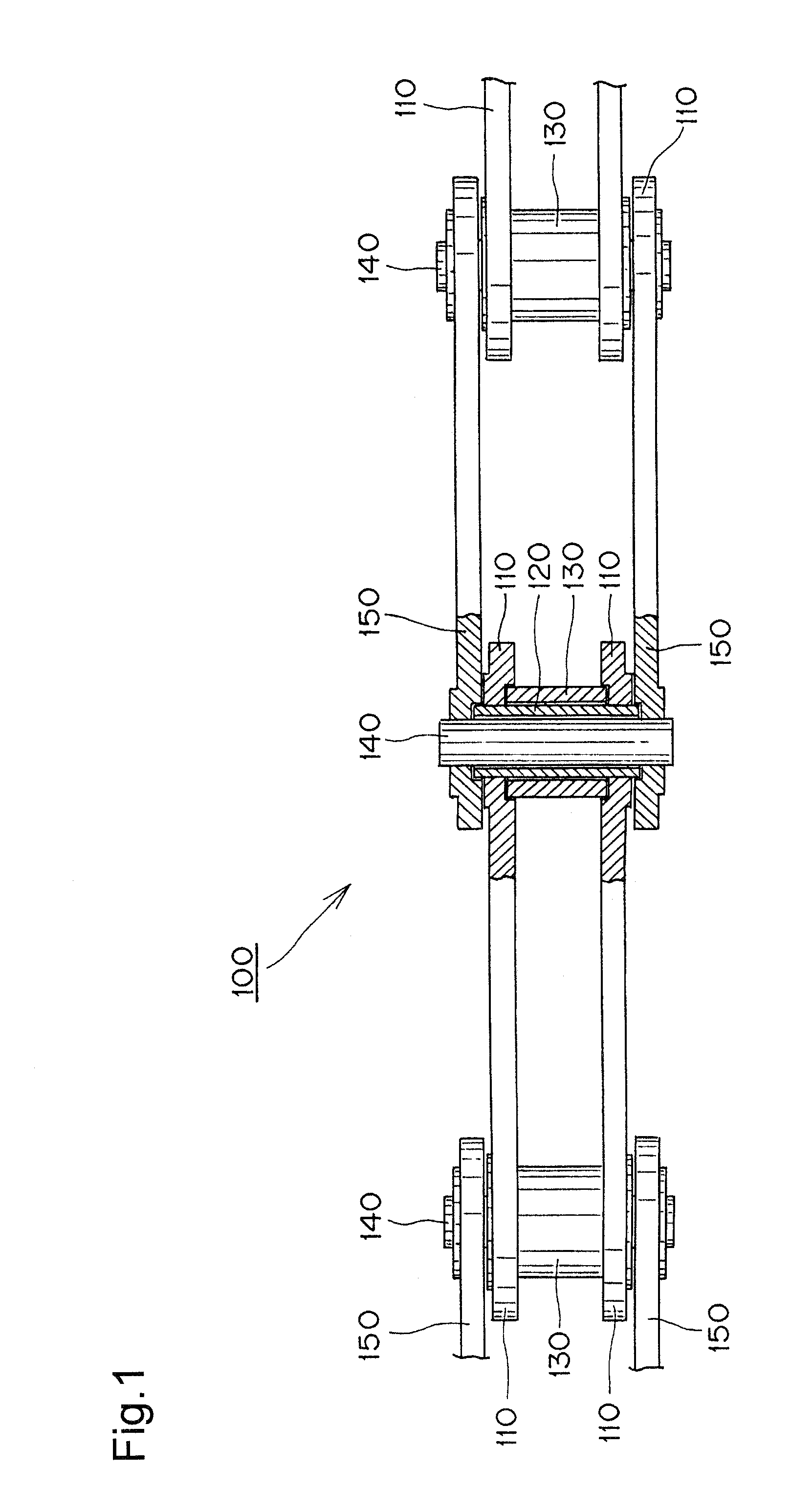
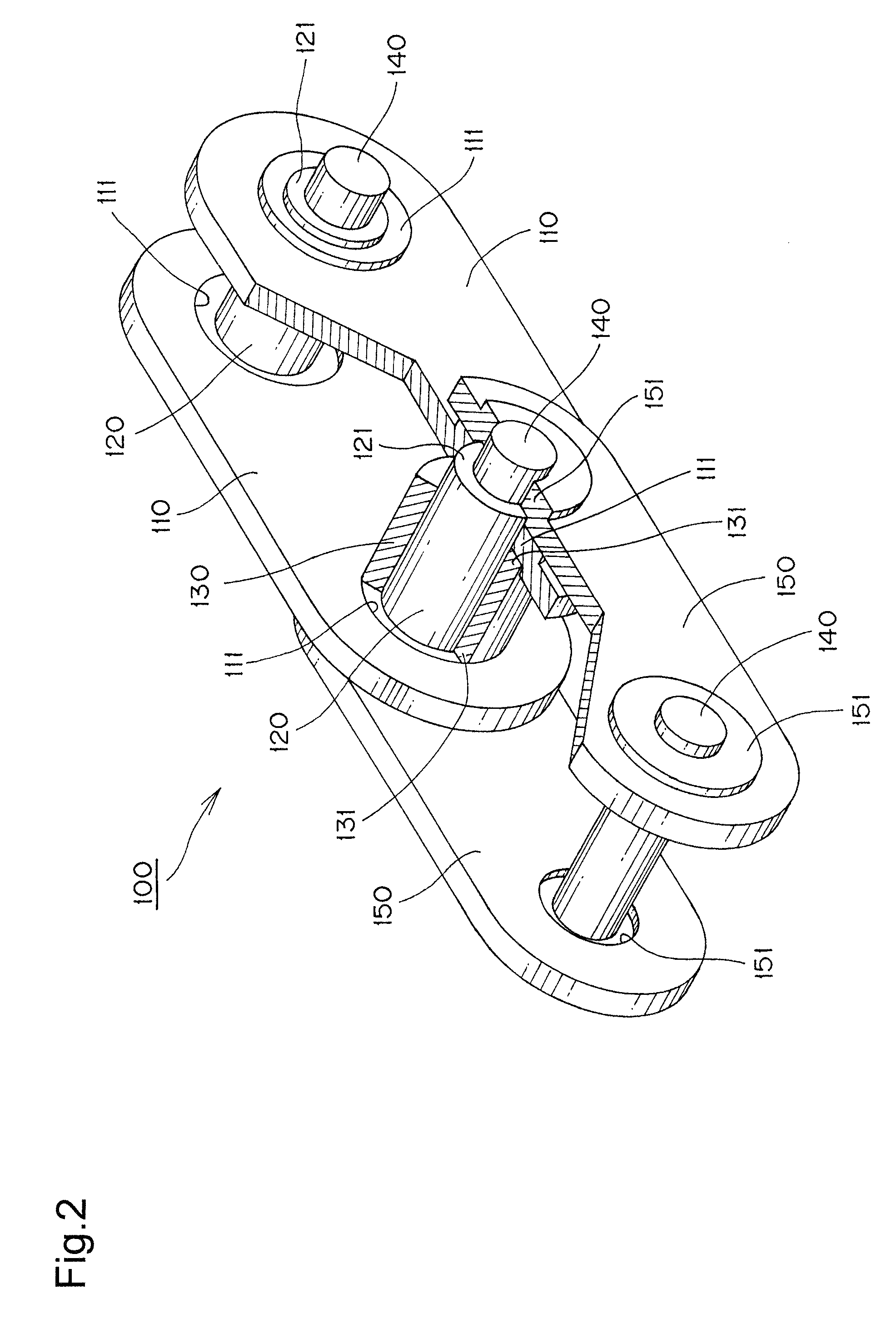
[0028]As stated previously, the roller chain of the invention is characterized by the fact that each of its bushings has end portions protruding from outside surfaces of the inner plates, and fitting into recesses formed in the inside surfaces of the outer plates. Furthermore, each roller has end portions fitting into recesses formed in the inside surfaces of the inner plates, each inner plate has a bulged portion coaxial with each recess in its inner surface and extending from its outer surface, and each outer plate has a bulged portion coaxial with each recess in its inner surface and extending from its outer surface. Preferably, the bulged portions are substantially cylindrical in shape.

[0029]Leakage of lubricating oil sealed between the connecting pins and the bushings and between the rollers and the bushings is avoided, and invasion of external dust is prevented. The avoidance of leakage and dust invasion is accomplished without reducing the strength of the chain, and sliding c...


PUM


Abstract

In an oil-free roller chain, the inner faces of the outer link plates have recesses that receive the ends of bushings, and the inner faces of the inner link plates have recesses that receive the ends of rollers surrounding the bushings. Each such recess is formed by punching, so that the outer surface of each plate has a bulged portion opposite each recess. The diameters of the bulged portions are greater than the diameters of the corresponding recesses. The bushing can have an oil passage located midway between its ends and serving as an oil reservoir supplying oil to the gap between the bushing and the roller and between the bushing and a connecting pin.

Description

CROSS-REFERENCE TO RELATED APPLICATION[0001]This application claims priority on the basis of Japanese patent application 2007-129569, filed May 15, 2007. The disclosure of Japanese application 2007-129569 is hereby incorporated by reference.FIELD OF THE INVENTION[0002]The invention relates to an oil-free chain, also known as a “seal chain,” for use in a conveyor for transferring articles, or for use as a power-transmitting roller chain or the like. The invention relates and more specifically to an oil-free chain comprising pairs of inner plates and pairs of outer plates in alternating, overlapping relationship along the length of the chain. In such a chain, a pair of bushings is provided for each pair of inner plates, and ends of the bushings are press-fit into bushing holes in the inner plates. A roller fits rotatably on each bushing. A pair of connecting pins is provided for each pair of outer plates, and the ends of the pins are press-fit into pin holes in the outer plates. Each ...

Claims


Application Information

Patent Timeline
Patent Type & Authority Patents(United States)
IPC IPC(8): F16G13/04
CPCF16G13/06F16G13/02
Inventor AOKI, TOSHIHIKOISHIDA, HIROKINAKAGAWA, TAKASHI
Owner TSUBAKIMOTO CHAIN CO
Why Eureka
Try Eureka