Liquid crystal display
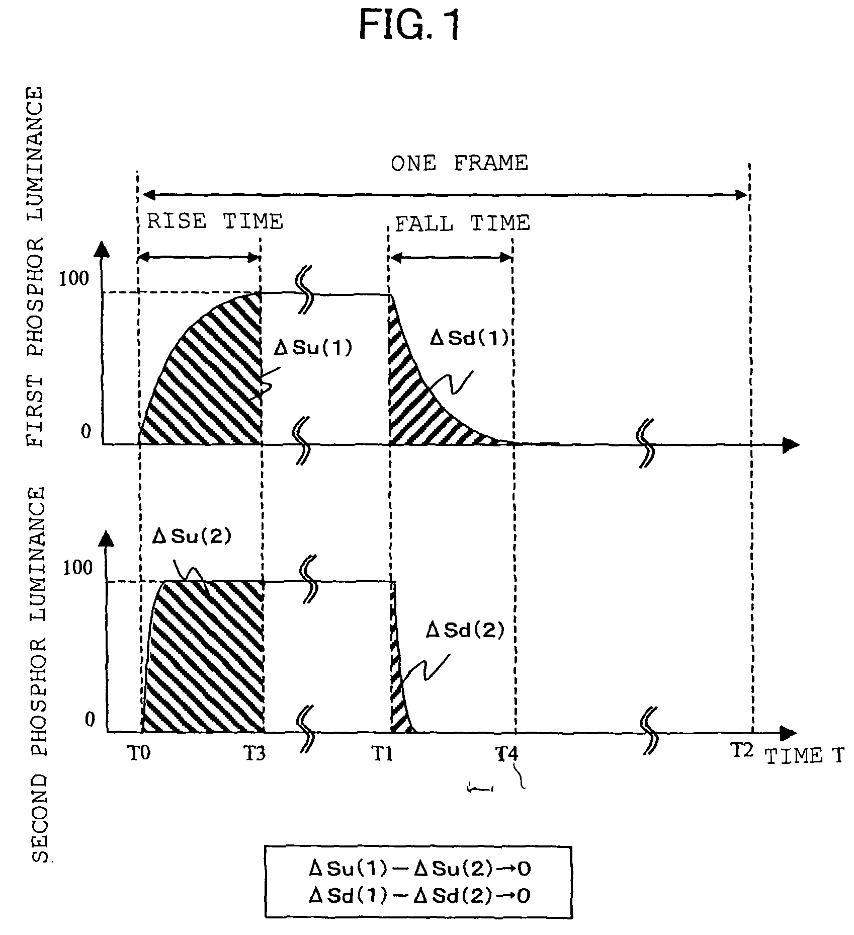
a liquid crystal display and liquid crystal technology, applied in the field of liquid crystal display, can solve the problems of image quality deterioration, display contents are blurred, and the performance of the liquid crystal display is inferior to that of the crt, and achieve the effects of improving the blurring of moving images, improving the “color misregistration” of luminance rise time and luminance fall time, and superior display performan
- Summary
- Abstract
- Description
- Claims
- Application Information
AI Technical Summary
Benefits of technology
Problems solved by technology
Method used
Image
Examples
embodiment 1
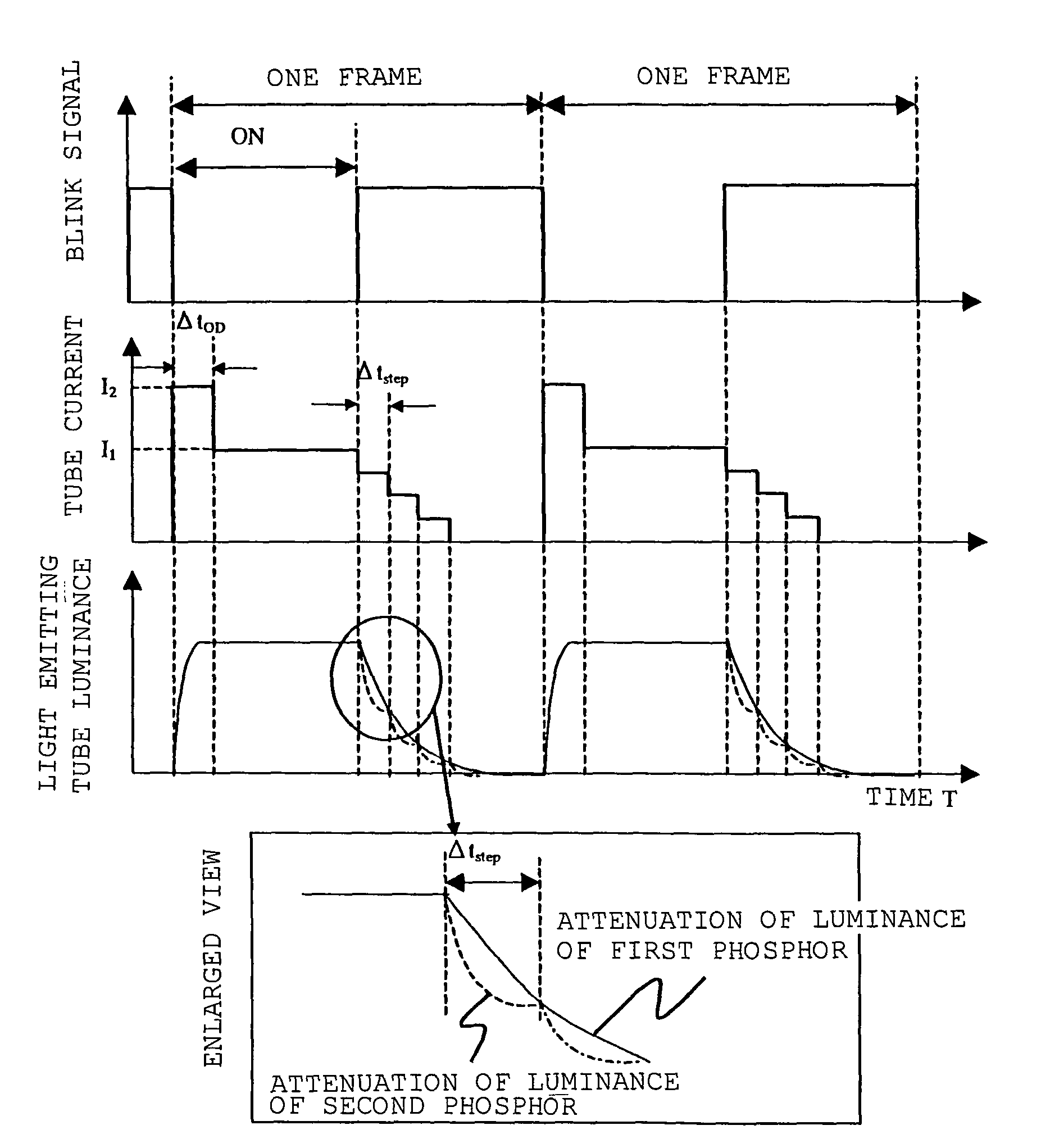
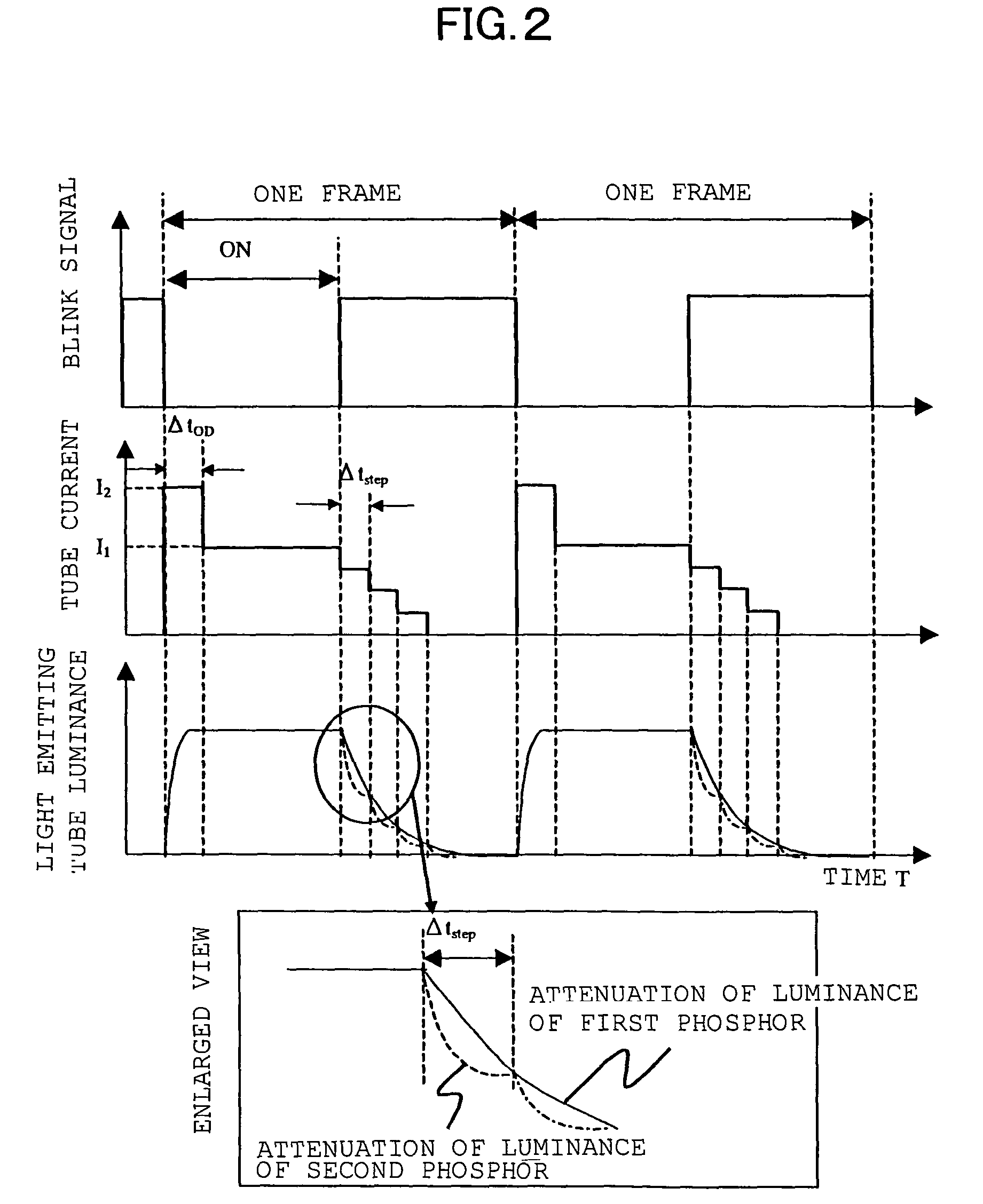
[0102]The outline of a liquid crystal display according to this embodiment is fundamentally similar to the background-art liquid crystal display shown in FIG. 19, but largely different from the background art in the waveform of a current to control the luminance of each fluorescent tube. FIG. 2 shows a blink signal waveform, a tube current waveform and a light emitting tube luminance response waveform in this embodiment.
[0103]In this embodiment, one kind of multicolor light source is used. Specifically, cold cathode fluorescent tubes internally applied with fluorescent materials of three colors (red, green and blue) are used as the light source. The waveform of a current applied to each of the cold cathode tubes is shown in FIG. 2.
[0104]Here, (Ba,Sr)MgAl10O17:Eu, Y2O3:Eu and LaPO4:Tb,Ce are used as blue, red and green fluorescent materials respectively. The luminance response speeds of these fluorescent materials are about 0.5 msec, 3 msec and 7 msec respectively.
[0105]As shown in F...
embodiment 2
[0108]This embodiment is different from Embodiment 1 only in the waveform of a current to control the luminance of each fluorescent tube. Particularly the current waveform is different in the luminance rise time. The blink waveform, the tube current waveform and the light emitting tube luminance response waveform in this embodiment will be described with reference to FIG. 4. In FIG. 5, the reference numeral 12A represents a first light emitting tube; 12B, a second light emitting tube; and 8A and 8B, inverters for driving the first light emitting tube 12A and the second light emitting tube 12B respectively. The same reference numerals as those in FIG. 19 correspond to the same parts as those in FIG. 19.
[0109]As shown in FIG. 4, in the luminance rise time, the current value is increased stepwise. In this event, the current value is set so that the step width of the current value has a time width Δtstep. It is important to set the time width Δtstep to be shorter than the response time ...
embodiment 3
[0113]The outline of a liquid crystal display according to this embodiment will be described with reference to the aforementioned FIG. 5. In the liquid crystal display according to this embodiment, two kinds of light emitting tubes, that is, a first light emitting tube 12A and a second light emitting tube 12B are used. These two kinds of light emitting tubes are connected to different inverter circuits 8 (8A and 8B), and controlled by one and the same blink signal from a blink signal generation circuit 9 shared by the inverter circuits 8.
[0114]The first light emitting tube 12A is applied with a red fluorescent material and a green fluorescent material having slow response speeds and having almost the same response time. On the other hand, the second light emitting tube 12B is applied with a blue fluorescent material having a fast response speed. Here, (Ba,Sr)MgAl10O17:Eu, Y2O3:Eu and LaPO4:Tb,Ce are used as the blue, red and green fluorescent materials respectively.
[0115]This embodi...
PUM
| Property | Measurement | Unit |
|---|---|---|
| luminance fall time | aaaaa | aaaaa |
| luminance fall response time | aaaaa | aaaaa |
| luminance fall response time | aaaaa | aaaaa |
Abstract
Description
Claims
Application Information
 - R&D
- Intellectual Property
- Life Sciences
- Materials
- Tech Scout
- Unparalleled Data Quality
- Higher Quality Content
- 60% Fewer Hallucinations
Browse by: Latest US Patents, China's latest patents, Technical Efficacy Thesaurus, Application Domain, Technology Topic, Popular Technical Reports.
© 2025 PatSnap. All rights reserved.Legal|Privacy policy|Modern Slavery Act Transparency Statement|Sitemap|About US| Contact US: help@patsnap.com


