Sensor device which measures surrounding conditions and obtains a newly measured value, retrieval device which utilizes a network to search sensor devices, and relay device which relays a communication between the sensor device and the retrieval device

a sensor device and surrounding condition technology, applied in the field of sensor devices, can solve the problems of increasing the load of the processor at the database side, preventing the scalability of the database, and not being able to solve the problem essentially

Active Publication Date: 2011-03-29
PANASONIC INTELLECTUAL PROPERTY CORP OF AMERICA
View PDF16 Cites 23 Cited by
  • Summary
  • Abstract
  • Description
  • Claims
  • Application Information

AI Technical Summary

Benefits of technology

[0026]In the case of the sensor network utilizing the aforementioned multi-cast communication, the retrieval node has to only transmit inquiry data for inquiring each channel of a measured temperature. The loads imposed on the network and the retrieval node will be reduced compared to the case of transmitting inquiry data to each sensor node.
[0053]The present invention provides a sensor device, a retrieval device, and a relay device with which it is possible to conduct a flexible search on sensor devices based on dynamic property, and to prevent the unnecessary loads imposed on the network and each of the devices due to the search.

Problems solved by technology

Therefore, the updated data from each sensor node concentrates on a band directly under the database system, which overloads the band, increases the load of the processor at the database side, and inhibits the securing of scalability.
It is therefore not possible to essentially solve the problems.
Moreover, the update interval cannot be made longer since the real-timeness of a measured value measured by a sensor is lost depending on the length of the update interval at which the database is updated.

Method used


Image

  • Sensor device which measures surrounding conditions and obtains a newly measured value, retrieval device which utilizes a network to search sensor devices, and relay device which relays a communication between the sensor device and the retrieval device
  • Sensor device which measures surrounding conditions and obtains a newly measured value, retrieval device which utilizes a network to search sensor devices, and relay device which relays a communication between the sensor device and the retrieval device
  • Sensor device which measures surrounding conditions and obtains a newly measured value, retrieval device which utilizes a network to search sensor devices, and relay device which relays a communication between the sensor device and the retrieval device

Examples


first embodiment

[0109]Firstly, the configuration of the sensor node and the retrieval node according to the first embodiment will be described with reference to FIGS. 2 through 4.

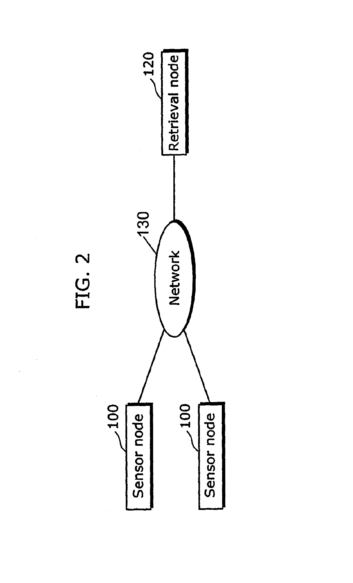
[0110]FIG. 2 is a diagram showing an outline configuration of the sensor network according to the first embodiment of the present invention.

[0111]As shown in FIG. 2, the sensor network according to the first embodiment is comprised of a retrieval node 120 and plural sensor nodes 100. The sensor node 100 is an example of the sensor device of the present invention whereas the retrieval node 120 is an example of the retrieval device of the present invention.

[0112]The retrieval node 120 and the sensor nodes 100 are connected to a network 130, and can communicate with each other. The network 130 is a network that has plural channels for the communication.

[0113]Note that the first through third embodiments below describe the case of using an Internet Protocol Version 6 (IPv6) network as the network 130.

[0114]FIG. 3 is a function...

second embodiment

[0252]The following describes an example of the sensor network for use in a physical distribution management system which uses wireless tags on which individual identification numbers are recorded. The wireless tags are tiny wireless IC chips to be used for the identification of the objects, and are also called “IC tags”, “RF tags”, and the like. A wireless tag has identification information of its own recorded and is capable of sending and receiving the information to and from the management system using electric waves.

[0253]The individual identification number of the wireless tag is identification information in accordance with the number system in which the uniqueness of the identification numbers is assured on a specific domain, as described above. An EPC to be used for RFID, or the like, can be raised as an example of such information.

[0254]The RFID is an individual identification number in a global domain which assures uniqueness. In the EPC, a number system management organiz...

third embodiment

[0285]The following describes, as the third embodiment of the present invention, an embodiment which enables a search across the sensor networks having the network address allocation policies which are different from each other.

[0286]FIG. 14 is a diagram showing an outline configuration of the sensor network according to the third embodiment.

[0287]The sensor network according to the third embodiment has the configuration in which a sensor network (SN2) on the IPv6 network 111, a sensor network (SN1) on a P2P network 703 and a sensor network (SN3) on an ad-hoc network 708 are respectively connected via a relay node 800. Note that the SN1 and SN2 are the examples of the first network and the second network in the relay device according to the present invention.

[0288]The sensor node 100 and the retrieval node 120 described in the first embodiment are connected to the SN2, and sensor nodes 100a and 100b having the same configuration as the sensor node 100 are respectively connected to t...


PUM


Abstract

The sensor device having an address storage unit 107 storing a channel address to be used, a temperature sensor 103, a table storage unit 101 storing an address table in which a measurement value is associated with a channel address, and an address specification unit 102 specifying a channel address associated with a measured value obtained from the temperature sensor 103. The sensor device also including an address update unit 105 updating the channel address in the address storage unit 107, a judgment unit 108 judging whether or not inquiry data is directed to the channel address stored in the address storage unit 107, a response generation unit 106 generating response data which is a response to the inquiry data, and a communication unit 109 transmitting the response data to a retrieval node 120.

Description

BACKGROUND OF THE INVENTION[0001]1. Field of Invention[0002]The present invention relates to a sensor device which measures surrounding conditions, a retrieval device which searches sensor devices via a network, and a relay device which relays between the sensor devices and the retrieval device.[0003]2. Description of the Related Art[0004]Conventionally, there has been provided a sensor network which is a network system for use in observing natural phenomena such as climate and temperature, surveying the conditions in the event of a natural disaster, and managing stocks. In the sensor network, an Internet Protocol (IP) network, for example, is used as a backbone for connecting each of the components such as a sensor and a database, in order to realize a wide range of services.[0005]For connecting a sensor to the network, a sensor node, which is a sensor device incorporating one or more sensors and a network communication function as one, is used.[0006]In order to make use of the sen...

Claims


Application Information

Patent Timeline
Patent Type & Authority Patents(United States)
IPC IPC(8): G06F15/16G08C15/00G08C17/02
CPCG08C17/00H04L45/16H04W40/246H04W8/26H04W40/20H04W84/18
Inventor ISHII, TOMOKI
Owner PANASONIC INTELLECTUAL PROPERTY CORP OF AMERICA
Why Eureka
Try Eureka