Eureka AIR delivers breakthrough ideas for toughest innovation challenges, trusted by R&D personnel around the world.

Constraining source code and objects for analysis tools

a source code and object technology, applied in the field of computer software, can solve the problems of hundreds or thousands of program instructions, hundreds of unwanted stoppages prior, and too much information being sent to the debuggers,

Active Publication Date: 2011-03-29
IBM CORP
View PDF23 Cites 33 Cited by
  • Summary
  • Abstract
  • Description
  • Claims
  • Application Information

AI Technical Summary

Problems solved by technology

The step operation provides a programmer with a large amount of information about a program during its execution but the task of stepping through hundreds or thousands of program instructions may be tedious and time consuming.
As mentioned, there can be many generic objects called many times in an application so that placing a conventional breakpoint in a routine of one of these generic objects will result in hundreds of unwanted stoppages prior to occurrence of a desired stoppage.
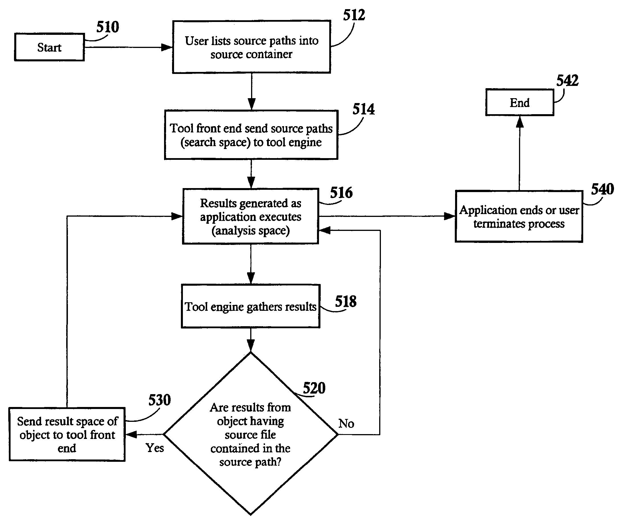
Despite context-specific breakpoints used in debuggers, too much information may be sent to the debuggers, i.e., the search space is too large for the expected task, and / or the tools return too much information to the developer, i.e., the result space is too massive to be useful, or may not be relevant to the developer's area of interest.
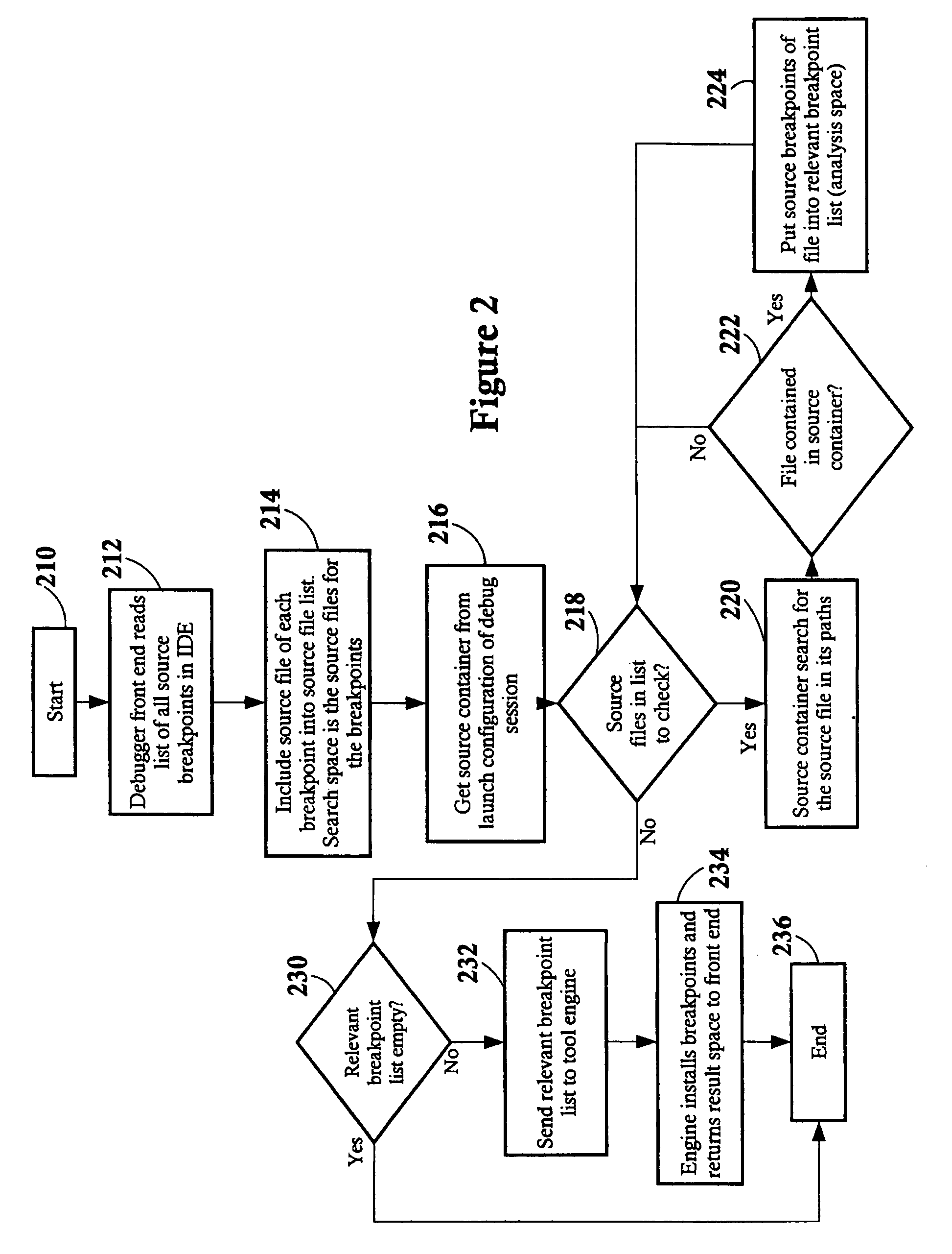
Thus, an analysis tool engine processes many source breakpoints a number of times despite the fact that most of them are not applicable to the source code being debugged.
As a result, a developer may not be able to debug code that comes from an outside project such as C / C++ standard library headers or code from a JAVA Runtime Environment (JRE).
Thus, this solution of limiting the scope of source breakpoints to a particular project does not address the whole problem for a real world application.
At all times, the fundamental object of analysis is the source code itself such that the source code ultimately limits the results of interest to a software developer.

Method used


Image

  • Constraining source code and objects for analysis tools
  • Constraining source code and objects for analysis tools
  • Constraining source code and objects for analysis tools

Examples


Embodiment Construction

[0025]The invention is described with reference to the accompanying drawings; however, the invention may be embodied in many different forms and should not be construed as limited to the embodiments set forth herein. Rather the illustrated embodiments are provided so that this disclosure is thorough and complete, and fully conveys the scope of the invention to those skilled in the art. Like numbers refer to like elements throughout.

[0026]As will be appreciated by one of skill in the art, the present invention may be embodied as a method, system, or computer program product. Accordingly, the present invention may take the form of an entirely hardware embodiment, an entirely software embodiment (including firmware, resident software, micro-code, etc.) or an embodiment combining software and hardware aspects all generally referred to herein as a “circuit” or “module.” Furthermore, the present invention may take the form of a computer program product on a computer-usable storage medium ...


PUM


Abstract

A source container for use in a computer system executing problem determination tools in an integrated environment across a computer network, the source container comprising a list of pathways to a plurality of source files and module objects. A software development may create the source container independently or within the front end of a problem determination tool. The front end of the problem determination tools sends the source container to its engine, and only source files and module objects having a pathway in the source container are analyzed within the engine of the problem determination tool. Furthermore, the results of the analysis of only those source files and module objects having a pathway in the source container are returned to the front end of the problem determination tool for viewing by the software developer. The front ends of the tools of the integrated development environment, the source files, the module objects, the engines of the tools, and different tools may all be located on different servers and / or clients across a computer network.

Description

CROSS-REFERENCE TO RELATED APPLICATIONS[0001]This invention relates to U.S. patent application Ser. No. 10 / 905,619 entitled METHOD, SYSTEM AND PROGRAM PRODUCT FOR LOCATING REMOTE SOURCE FILES filed 13 Jan. 2005, commonly owned by the assignee.BACKGROUND OF THE INVENTION[0002]This invention relates generally to the field of developing computer software in integrated development environments and more particularly relates to constraining the amount of source code used by runtime analysis tools.[0003]Computer software development has its own terminology and, herein at the beginning, a tutorial in definitions as used herein may be helpful. Software is object code and source code. Object code is the output from a compiler or assembler and is the code that is executable by the computer machine itself or can be used to create executable machine code. Source code is the input to a compiler or assembler typically written by a human in a source language, such as C++ or JAVA, and is capable of ...

Claims


Application Information

Patent Timeline
Patent Type & Authority Patents(United States)
IPC IPC(8): G06F9/44
CPCG06F11/3624
Inventor CHEN, XUAN ZHANGMUNIR, KUSHAL SAYEEDMCKNIGHT, DAVID KENNETHDING, LIBERESTETSKY, VADIM
Owner IBM CORP
Why Eureka
Eureka Blog
Learn More