Cutting tools having lighting devices

a technology of lighting device and cutting tool, which is applied in the field of cutting tools, can solve the problems of affecting the effect of lighting device damage, affecting the performance of lighting device, and likely receiving a relatively large impact force on the pivotable arm, so as to achieve the effect of protecting the lighting device from damag

Inactive Publication Date: 2011-04-05
MAKITA CORP
View PDF16 Cites 9 Cited by
  • Summary
  • Abstract
  • Description
  • Claims
  • Application Information

AI Technical Summary

Benefits of technology

[0007]It is, accordingly, one object of the present invention to teach improved cutting tools that can more effectively protect a lighting device from damage due to an accidental external force that may be applied to the cutting tool.
[0008]According one aspect of the present teachings, cutting tools arc taught that provide increased durability for a lighting device. For example, cutting tools are taught that may include a lighting device that is mounted on a tool unit adjacent to a grip portion (or auxiliary handle portion). In this case, the grip or auxiliary handle portion will protect the lighting device from being damaged, in the event that an external force is applied to the cutting tool. Therefore, possible damage to the lighting device can be minimized or prevented, even if the cutting tool is accidentally dropped.
[0009]In another aspect of the present teachings, the lighting device may be mounted on a motor case (motor housing), such as at a joining portion (joining surface) that is defined on the motor case for joining or attaching the motor case to a blade case (blade housing). The joining portion may preferably be designed so as to have a strength that is greater than the other portions of the motor case. Therefore, the lighting device can be protected from externally applied forces by disposing the lighting device at or near the joining portion.
[0010]In another aspect of the present teachings, a shoe (base) may be coupled to the tool unit via a mount (support arm) that extends from a portion of the motor case. The lighting device may be disposed at a portion of the cutting tool that is between the grip or auxiliary handle portion and the mount, which parts may constitute two projections extending from the motor case. Therefore, it is possible to significantly reduce (or eliminate) the possibility that the lighting device will contact an external object, such as a floor of a workplace, in the event that the cutting tool is accidentally dropped.

Problems solved by technology

However, because the pivotal arm is positioned so as to extend from the motor case, the pivotable arm naturally has relatively low strength or low durability.
Thus, if the circular saw is, e.g., accidentally dropped, the pivotable arm will likely receive a relatively large impact force due to its configuration and the mounted position.
As a result, a possibility exists that the pivotable arm will be damaged and the lighting device will be exposed to the outside if the circular saw happens to be dropped.

Method used


Image

  • Cutting tools having lighting devices
  • Cutting tools having lighting devices
  • Cutting tools having lighting devices

Examples


Embodiment Construction

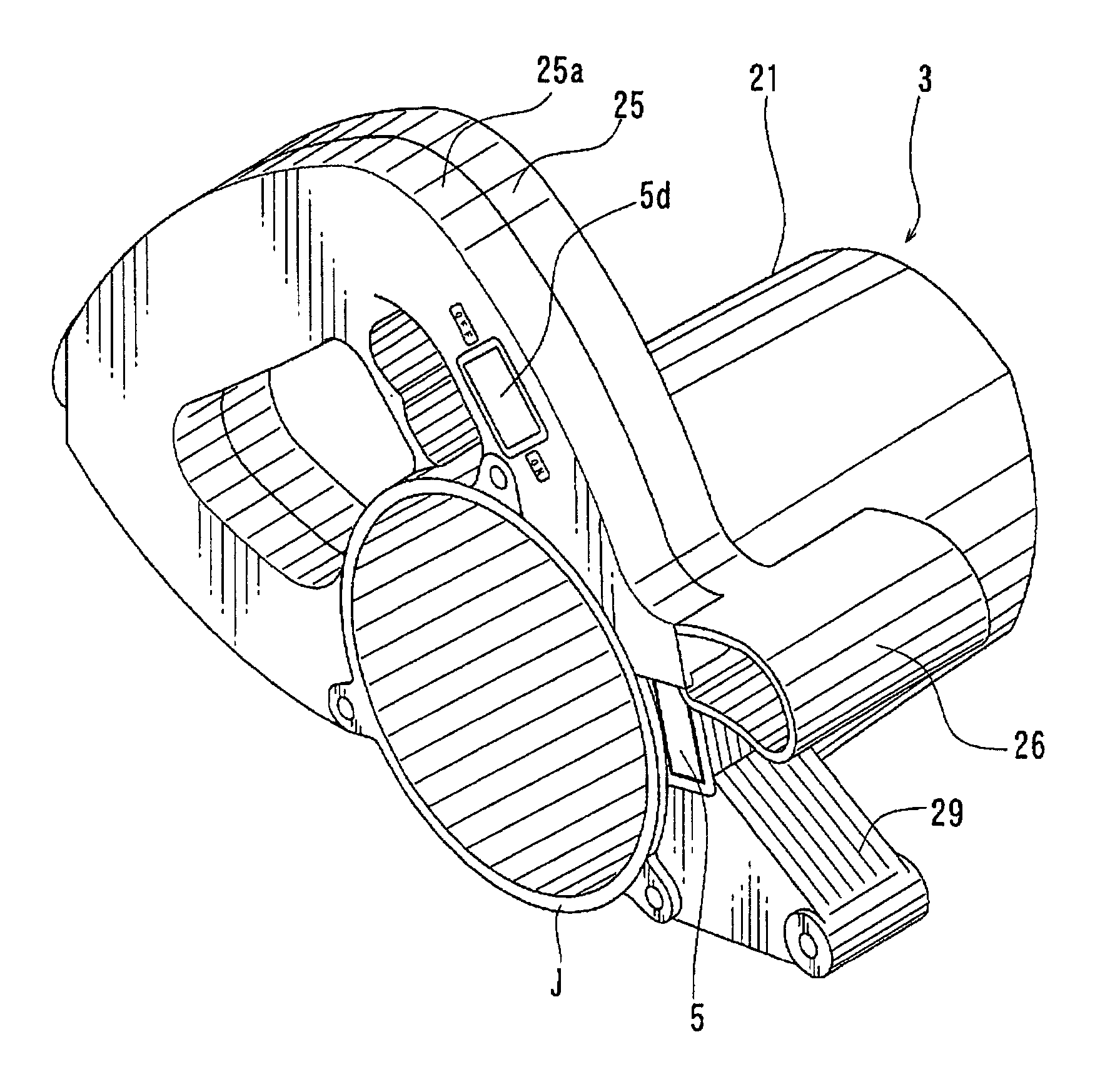
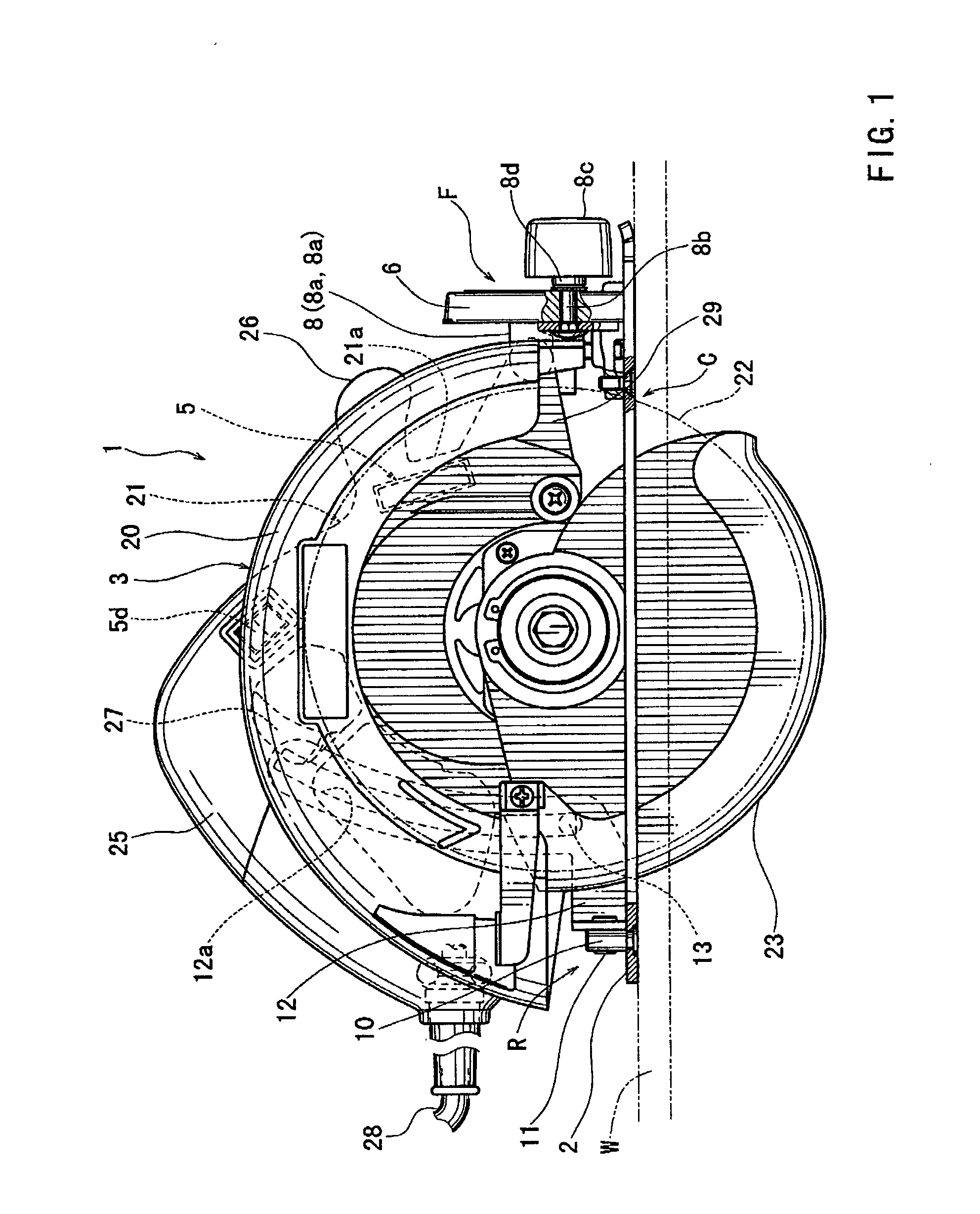
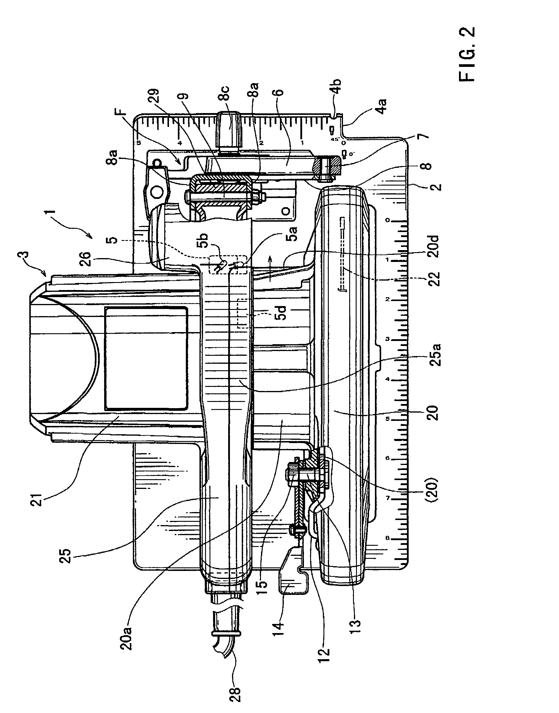
[0018]Cutting tools are taught that include a motor case (motor housing) and a blade case Glade housing). The motor case may accommodate a motor and may include a joining portion (joining surface) that is designed to be joined or affixed to the blade case. A grip portion (auxiliary handle) may extend from the motor case and is preferably designed to be grasped by an operator of the cutting tool. The grip portion may include a grip base defined on one side of the motor case. A lighting device may be disposed on the motor case in a position that is adjacent or proximal to both the joining portion and the grip base. The joining portion preferably is designed so as to be more resilient (durable) or stronger than the other portions of the motor case. Preferably, the grip portion may be designed so as to contact the floor before the lighting device contacts the floor, in the -event that the cutting tool is accidentally dropped. In this case, the lighting device can be reliably protected s...


PUM

PropertyMeasurementUnit
angleaaaaaaaaaa
transparentaaaaaaaaaa
areasaaaaaaaaaa

Abstract

Cutting tools (1) may include a lighting device (5). The lighting device may be mounted on a tool unit (3) adjacent to a grip portion (26). Preferably, the grip portion serves to protect the lighting device from being damaged by an external force. The tool unit may include a motor case (21) for accommodating a motor. The grip portion may extend from the motor case and the lighting device may be mounted on or within the motor case. The tool unit may further include a blade case (20) that at least partly covers a cutting blade (22). The blade case may be joined to the motor case via a joining portion J defined on the motor case. In this case, the lighting device is preferably disposed proximal to the joining portion. The lighting device may include at least a first light (5a) and a second light (5b) that are arranged and constructed to illuminate different areas.

Description

[0001]This application claims priority to Japanese patent application serial number 2001-236417, which was filed Aug. 3, 2002, the contents of which are incorporated herein by reference.BACKGROUND OF THE INVENTION[0002]1. Technical Field[0003]The present invention relates to cutting tools, such as portable circular saws, and more particularly, to cutting tools having one or more lights that serve to illuminate an area around a portion of a workpiece, e.g., a portion of a workpiece that will be cut during a cutting operation.[0004]2. Description of the Related Art[0005]Japanese Laid-Open Patent Publication No. 11-170203 teaches a portable circular saw that includes a lighting device. The lighting device is mounted on a front portion of a saw unit and is disposed laterally of a portion of a workpiece that will be cut by a front or leading portion of a circular saw blade. More specifically, the lighting device is disposed on a pivotal support that is mounted on a base (shoe) of the cir...

Claims


Application Information

Patent Timeline
Patent Type & Authority Patents(United States)
IPC IPC(8): B27B9/00B23D59/00B23Q17/24B25F5/02B27B9/02F21V29/00F21V33/00F21W131/403F21Y101/02
CPCB23D59/00B23Q17/2404B27B9/02F21V33/0084B25F5/021F21Y2101/02F21Y2115/10Y10T83/4795Y10T83/828Y10T83/9464
Inventor FUKUOKA, TORU
Owner MAKITA CORP
Why Eureka
Try Eureka