Construction spacer

a construction spacer and spacer technology, applied in the field of spacers, can solve the problems of aesthetic and/or functional undesirable effects, undue distortion of the vertical panel b>20/b>, etc., to reduce or eliminate such distortion and reduce the effect of distortion

Inactive Publication Date: 2011-04-05
COTTEN KENNETH K
View PDF17 Cites 17 Cited by
  • Summary
  • Abstract
  • Description
  • Claims
  • Application Information

AI Technical Summary

Benefits of technology

[0011]The prior art spacer 10 shown in FIG. 1 suffers from the drawback that coupling one panel to another panel merely by a bend can allow flexure occurring in one panel, e.g., panel 15, to cause the other panel, e.g., panel 20, to distort to an undue degree. To help reduce or eliminate such distortion, the present invention physically couples a first panel to a second panel to form a spacer device for construction, yet allows flexure to occur in the first panel without causing the second panel to distort to an undue degree. Such coupling advantageously allows one panel of the spacer to flex to conform to irregularities that may be in a footing yet helps prevent such flexure from causing the other panel of the spacer to distort to an undue degree. In preferred embodiments, this is achieved by coupling the panels together with a compressible hinge structure that helps to absorb distortion forces and substantially reduce distortion that might otherwise be induced among coupled panels.
[0012]It has also been discovered that providing a plurality of elongated dimples on a panel can help control the flexibility and rigidity in the panel. For example, a plurality of elongated dimples on a spacer panel can provide a desired level of flexibility and rigidity in the panel. Staggering and / or overlapping dimples such as elongated dimples in one or more directions can also help control rigidity. For example, elongated dimples can be staggered or overlapped longitudinally along a panel and / or across the width of a panel. In general, the more the dimples are staggered and / or overlapped, the more rigid the panel is. Advantageously, such a panel is flexible enough to properly conform to the wall yet rigid enough to support the panel between the floor and the wall to create a fluid-flow space between the floor and wall and rigid enough to resist undue distortion if the other panel of the spacer flexes. As another advantage, elongated dimples can make trowelling cement adjacent the dimples easier.

Problems solved by technology

The invasion of ground water into basements and other structures can cause numerous problems.
A drawback of many spacers (e.g., spacer 10) is that if panel 15 flexes to conform to the irregularities in footing 50, such flexure tends to be transferred to and can cause vertical panel 20 to distort to an undue degree.
Undue distortion in panel 20 can be aesthetically and / or functionally undesirable.
This makes panel 20 unsightly and has been a significant barrier against commercial acceptance of this prior art device.

Method used


Image

  • Construction spacer
  • Construction spacer
  • Construction spacer

Examples


Embodiment Construction

[0033]The embodiments of the present invention described below are not intended to be exhaustive or to limit the invention to the precise forms disclosed in the following detailed description. Rather a purpose of the embodiments chosen and described is so that the appreciation and understanding by others skilled in the art of the principles and practices of the present invention can be facilitated.

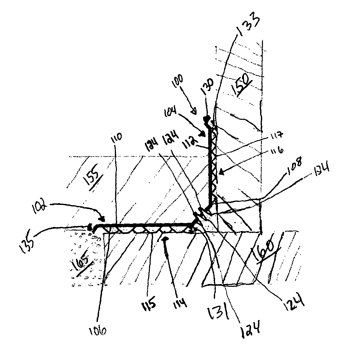
[0034]In general, spacers according to the present invention can be used to create fluid flow space at a variety of structural interfaces in construction. One particularly useful context in which spacers of the present invention can be used is in proximity to a concrete footing, concrete wall, and concrete floor (e.g., in a basement). Here, an L-shaped spacer of the present invention can form a space between the edge of a basement floor and the wall, and between at least part of the footing and the concrete floor. These spaces allow water (e.g., from the perimeter and the walls) to flow in...


PUM


Abstract

The present invention is related to spacers that can create fluid flow space at a variety of structural interfaces, particularly in building construction. The spacers of the present invention include unique hinges that can physically couple one panel of the spacer to another panel of the spacer in a manner that substantially distortionally separates the two panels. Preferred embodiments include a folded hinge having at least two folds. The spacers of the present invention also include unique panel dimples that help control the rigidity of the panel. In preferred embodiments, elongated dimples are used to help control rigidity.

Description

PRIORITY CLAIM[0001]The present non-provisional patent application claims priority under 35 USC §119(e) from U.S. Provisional Patent Application having Ser. No. 60 / 634,880, filed on Dec. 10, 2004, by Cotten and titled CONSTRUCTION SPACER, wherein the entirety of said provisional patent application is incorporated herein by reference.FIELD OF THE INVENTION[0002]The present invention is related to spacers that can create fluid flow space at a variety of structural interfaces, particularly in building construction. For example, spacers according to the present invention can be used to create water-flow spaces between the edge of a floor and a wall and between a footing and the floor to help manage water around building foundations.BACKGROUND OF THE INVENTION[0003]The invasion of ground water into basements and other structures can cause numerous problems. Generally such water seeps into basements from the walls and perimeter of the floor at the floor-wall and wall-footing interfaces, a...

Claims


Application Information

Patent Timeline
Patent Type & Authority Patents(United States)
IPC IPC(8): E02D19/00E04B5/00E04B1/70
CPCE04B1/7023E02D31/02
Inventor COTTEN, KENNETH K.
Owner COTTEN KENNETH K
Why Eureka
Try Eureka