Method of reducing the fractional spurious and a fractional N-PLL oscillator reducing the fractional spurious

a fractional n-pll and oscillator technology, applied in the direction of electrical equipment, pulse automatic control, etc., can solve the problems of fractional spurious, and achieve the effect of reducing fractional spurious, less space, and reducing fractional spurious in fractional n-pll

Inactive Publication Date: 2005-12-22
AGILENT TECH INC
View PDF4 Cites 6 Cited by
  • Summary
  • Abstract
  • Description
  • Claims
  • Application Information

AI Technical Summary

Benefits of technology

[0012] The present invention provides a phase comparator with which the fractional spurious in a fractional N-PLL can be reduced when compared to the prior art. By means of the present invention, the additional circuits for reducing the fractional spurious require less space.

Problems solved by technology

It became clear that this fractional spurious is caused by the distortion component that is produced when the signals input to a phase comparator and the VCO output signals connected to the phase comparator and to the circuit around the phase comparator through the route that wasn't intended are intermodulated.

Method used


Image

  • Method of reducing the fractional spurious and a fractional N-PLL oscillator reducing the fractional spurious
  • Method of reducing the fractional spurious and a fractional N-PLL oscillator reducing the fractional spurious
  • Method of reducing the fractional spurious and a fractional N-PLL oscillator reducing the fractional spurious

Examples


first embodiment

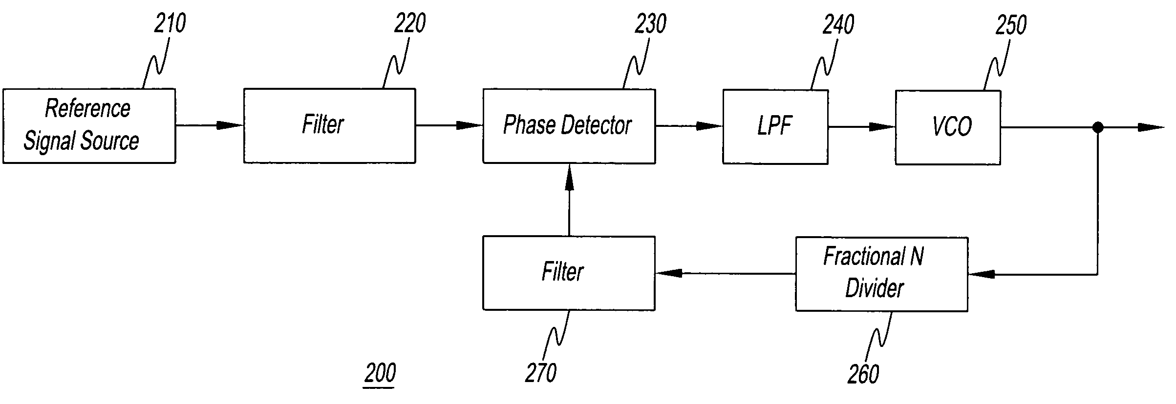
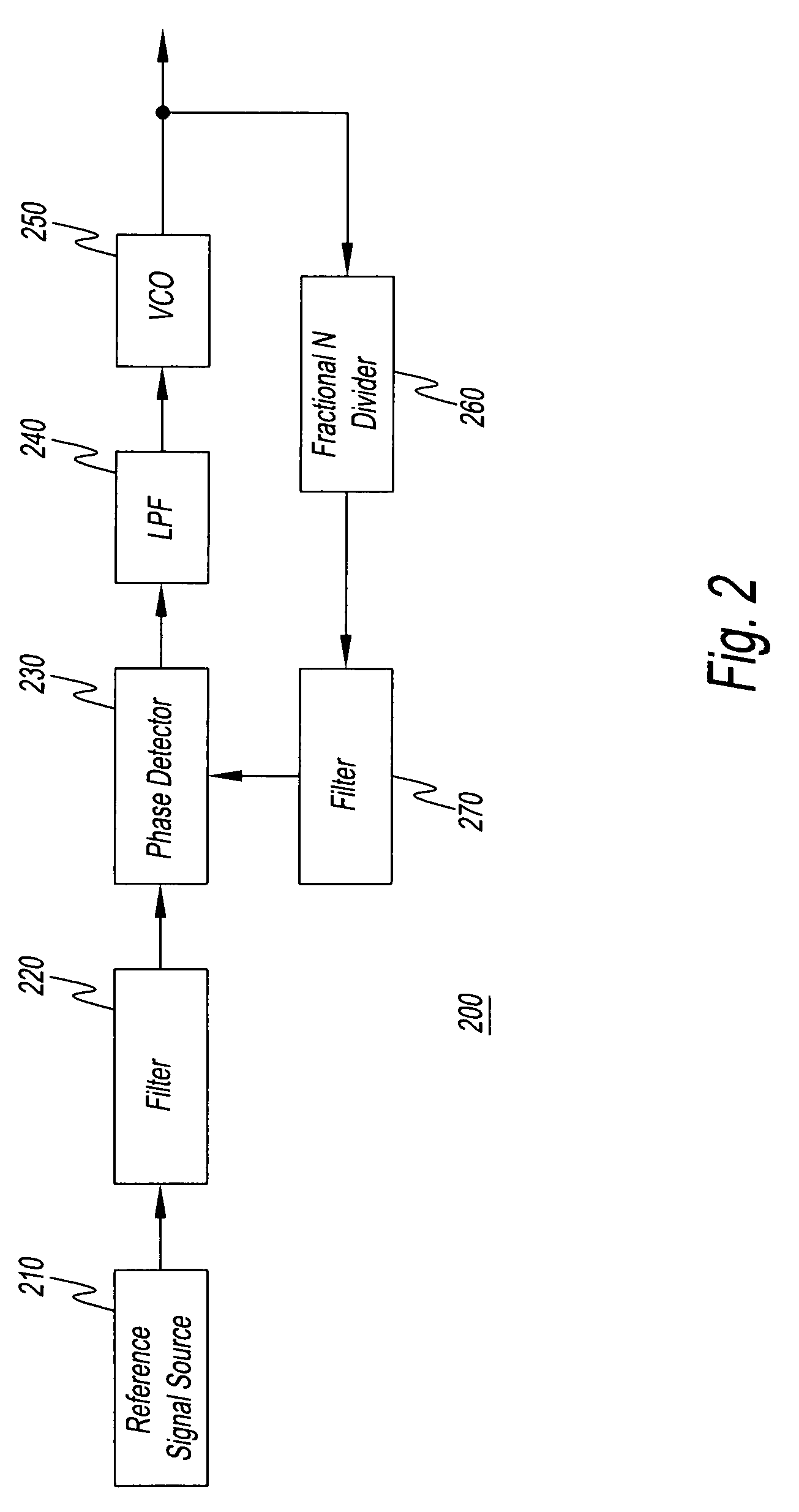
[0019] Preferred embodiments of the present invention will now be described while referring to the attached drawings as necessary. the present invention is a fractional N-PLL oscillator 200. FIG. 2 is a block diagram showing the general structure of fractional N-PLL oscillator 200. Fractional N-PLL oscillator 200 in the drawing comprises a reference signal source 210, a filter 220, a phase comparator 230, an LPF 240, a VCO 250, a fractional N divider 260, and a filter 270. The output signals of reference signal source 210 are input via filter 220 to phase comparator 230. The output signals of fractional N divider 260 are input via filter 270 to phase comparator 230. Phase comparator 230 detects the phase difference between these two input signals. The output signals of phase comparator 230 are input via LPF 240 to VCO 250. VCO 250 is an oscillator that varies its oscillation frequency in accordance with input signals. In short, VCO 250 varies the oscillation frequency in response to...

second embodiment

[0026] However, there are cases in which the oscillation frequency of VCO 250 and the frequency of the output signals of reference signal source 210 are similar and cases in which the anticipated properties are not obtained with filter 220 and filter 270. In other words, there are cases wherein the oscillation frequency component (output signal component) of VCO 250 cannot be thoroughly eliminated from the output signals of reference signal source 210 and the output signals of fractional N divider 260 and the fractional spurious cannot be eliminated as expected. the present invention that solves such problems is described below.

[0027] The second embodiment of the present invention is a fractional N-PLL oscillator 300. FIG. 4 is a block diagram showing the general structure of fractional N-PLL oscillator 300. The elements in FIG. 4 that are the same as in FIG. 2 are represented by the same symbols and are not described again. Fractional N-PLL oscillator 300 in the drawing comprises a...


PUM


Abstract

A method for reducing the fractional spurious in a fractional N-PLL oscillator comprising a phase comparator having nonlinear elements and a variable frequency oscillator that responds to the low frequency component of output signals of the phase comparator and with which reference signals and signals obtained by dividing the output signals of the variable frequency oscillator are input to the phase comparator, wherein the oscillation frequency component of the variable frequency oscillator is eliminated from the signals input to the phase comparator and the fractional spurious is thereby reduced. The oscillation frequency component of the variable frequency oscillator is eliminated using a gate in the drawings.

Description

FIELD OF THE INVENTION [0001] The present invention pertains to a fractional N-PLL circuit. DISCUSSION OF THE BACKGROUND ART [0002] The phase comparator is an indispensable structural element of the phase-locked loop (PLL). Phase comparators are one of the factors involved in the generation of a spurious signal component or spurious that results in a reduction in the S / N ratio of output signals of the PLL. For years attempts have been made to reduce the spurious attributed to phase comparators (for instance, refer to JP (Kokai) 11[1999]-74,734 (page 3, FIG. 3)). [0003] The fractional N-PLL is a type of PLL. A block diagram showing the general structure of a fractional N-PLL oscillator is shown in FIG. 1. A fractional N-PLL oscillator 100 in the drawing comprises a reference signal source 110, a phase comparator 120, a low pass filter 130, a voltage controlled oscillator 140, and a fractional N divider 150. The voltage controlled oscillator is hereafter referred to as a “VCO.” Moreov...

Claims


Application Information

Patent Timeline
Patent Type & Authority Applications(United States)
IPC IPC(8): H03L7/00H03L7/197
CPCH03L7/1974
Inventor ROPPONGI, SATOSHI
Owner AGILENT TECH INC
Why Eureka
Try Eureka