Method of sintering

a technology of metal injection moulding and aerofoil, which is applied in the direction of lighting and heating apparatus, turbines, furnaces, etc., can solve the problems of component distorted as it shrinks, component shrinkage, and component unwanted distortion, so as to reduce the unwanted distortion of components during sintering

Inactive Publication Date: 2016-10-20
ROLLS ROYCE PLC
View PDF7 Cites 5 Cited by
  • Summary
  • Abstract
  • Description
  • Claims
  • Application Information

AI Technical Summary

Benefits of technology

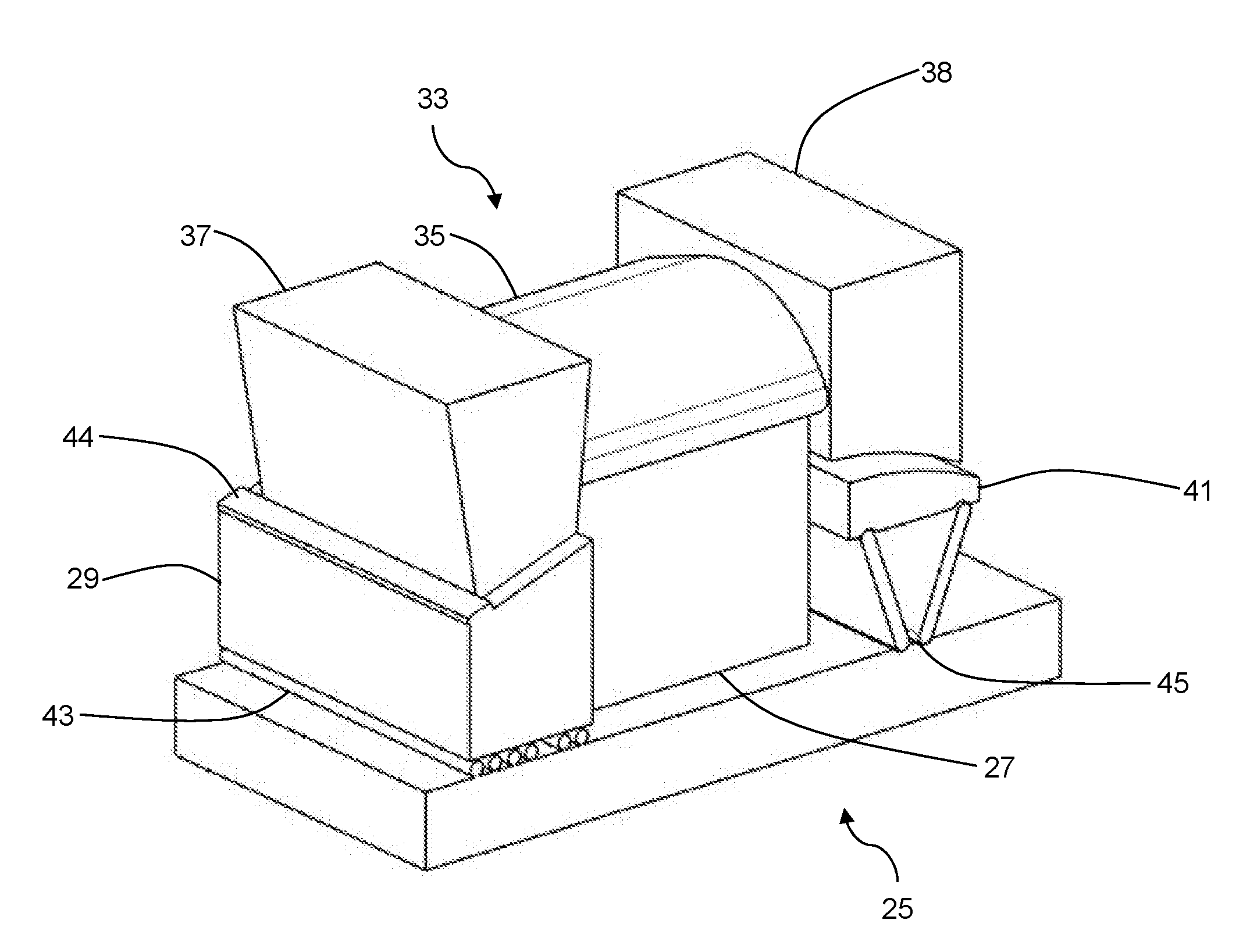
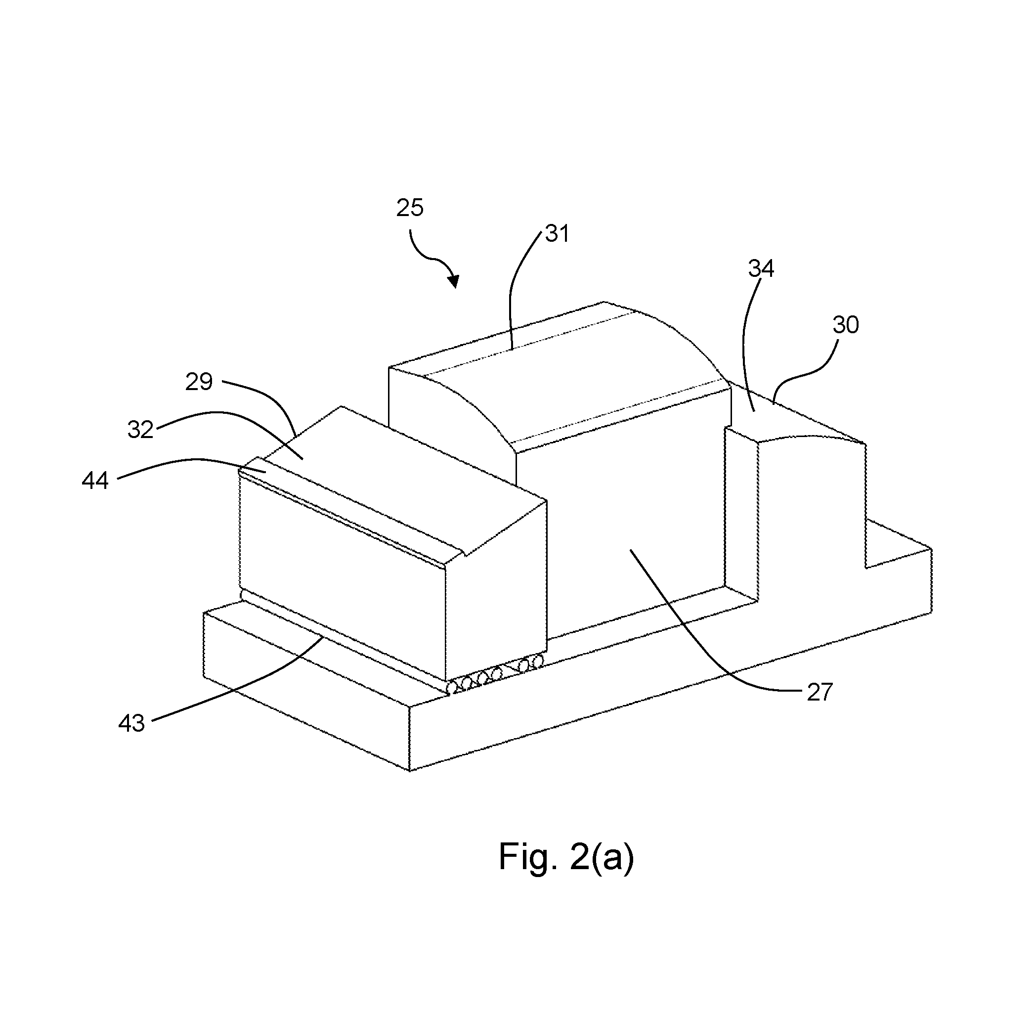
[0013]Advantageously, because the moveable platform is independently moveable relative to the stationary support, the method can thus reduce or eliminate unwanted distortion of components during sintering.
[0017]The method may further include: removing the sintered aerofoil component from the setter, and repeating the locating and sintering steps with another metal injection-moulded, green aerofoil component. Advantageously, the setter can thus be reused and the method can reduce the amount of waste material generated during MIM and reduce the amount of variation between separately sintered aerofoil components.
[0020]More generally, the moveable platform may be constrained to move in a plane or along a path defined by a line or curve. This can reduce unwanted distortion of components during sintering.
[0021]The setter may have a stopper against which the green component is located. This can help to ensure that the green component is correctly positioned on the setter.

Problems solved by technology

The fusing of the powder particles during sintering results in the green component shrinking.
If the entire component or isolated areas of the component are prevented from moving freely, the component can become distorted as it shrinks.
However the beads may move unevenly as they slide over each other or even seize up at high temperature, locally preventing free movement of the green component and leading to unwanted distortion of the component.
Further, the beads may not provide sufficient support to prevent deformation of thin sections under their own weight.
However, both of these setters are made from a powder and a binder which undergo sintering, thus they can only be used in a single sintering operation.

Method used


Image

  • Method of sintering
  • Method of sintering
  • Method of sintering

Examples


Embodiment Construction

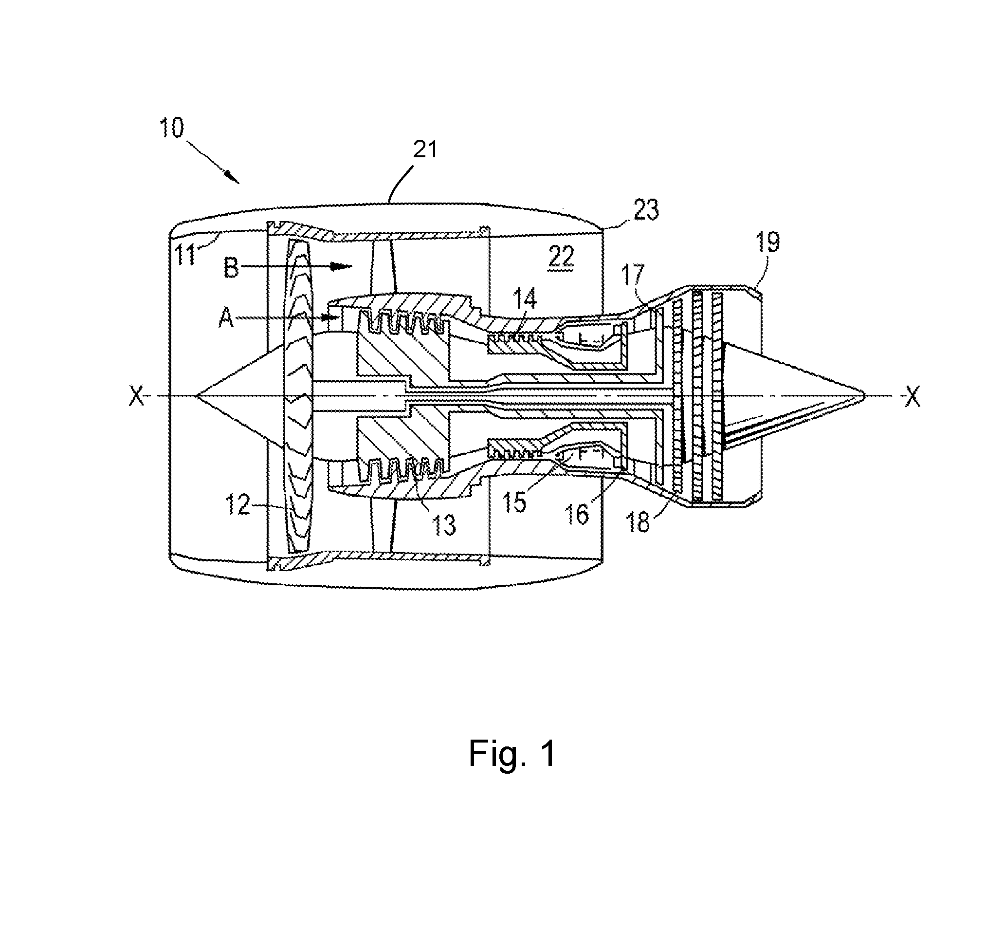
[0028]With reference to FIG. 1, a ducted fan gas turbine engine is generally indicated at 10 and has a principal and rotational axis X-X. The engine comprises, in axial flow series, an air intake 11, a propulsive fan 12, an intermediate pressure compressor 13, a high-pressure compressor 14, combustion equipment 15, a high-pressure turbine 16, an intermediate pressure turbine 17, a low-pressure turbine 18 and a core engine exhaust nozzle 19. A nacelle 21 generally surrounds the engine 10 and defines the intake 11, a bypass duct 22 and a bypass exhaust nozzle 23.

[0029]During operation, air entering the intake 11 is accelerated by the fan 12 to produce two air flows: a first air flow A into the intermediate-pressure compressor 13 and a second air flow B which passes through the bypass duct 22 to provide propulsive thrust. The intermediate-pressure compressor 13 compresses the air flow A directed into it before delivering that air to the high-pressure compressor 14 where further compres...


PUM

PropertyMeasurementUnit
diameteraaaaaaaaaa
shrinkageaaaaaaaaaa
shapeaaaaaaaaaa

Abstract

A method of sintering a metal injection-moulded, green aerofoil component. The method includes providing a setter having a stationary support arranged to support an aerofoil part of the component and a moveable platform arranged to support an end part of the component, the moveable platform being independently moveable relative to the stationary support. The method further includes locating the green component on the setter such that the aerofoil part and the end part are supported by respectively the stationary support and the moveable platform. The supported green component is then sintered, the moveable platform moving during the sintering relative to the stationary support to accommodate sintering-induced shrinkage of the component.

Description

CROSS-REFERENCE TO RELATED APPLICATIONS[0001]This application is based upon and claims the benefit of priority from British Patent Application Number 1506484.3 filed 16 Apr. 2015, the entire contents of which are incorporated by reference.BACKGROUND[0002]1. Field of the Disclosure[0003]The present disclosure relates to a method of sintering a metal injection-moulded, green aerofoil component.[0004]2. Description of the Related Art[0005]Metal Injection Moulding (MIM) is a metalworking process which produces components from a range of materials including steel, molybdenum, nickel, titanium and copper. The MIM process involves mixing a metal powder with a plasticising binder and injecting the resulting feedstock into a mould. The mould is then removed to leave a metal powder “green” component held together by the binder. The green component may undergo some intermediate processing but eventually undergoes sintering, sometimes with the application of additional pressure, to fuse the pow...

Claims


Application Information

Patent Timeline
Patent Type & Authority Applications(United States)
IPC IPC(8): B22F3/00B22F3/22B22F5/04
CPCB22F3/003B22F3/225B22F5/04B22F3/10B22F2999/00F27D5/00B22F2003/1042
Inventor DERGUTI, FATOSTODD, IAINCENDROWICZ, ALEKSANDER M.POUS ROMERO, HECTOR
Owner ROLLS ROYCE PLC
Why Eureka
Try Eureka