
Device for reduction of angular distortion in photograpy

Active Publication Date: 2011-08-16
SMITH ELIZABETH RUTH
View PDF20 Cites 6 Cited by
  • Summary
  • Abstract
  • Description
  • Claims
  • Application Information

AI Technical Summary

Benefits of technology

[0026]There is a general need for improving the standardization of photographic records of evidence. In particular, the standard handling of photographic scales may eliminate distortion, improve the accuracy of photographic evidence, and enhance its usefulness in photogrammetry. For bitemark cases in particular, the reduction of distortion would improve evidence quality, completeness, reliability, and validity of bitemark documentation.
[0027]Therefore, the present invention relates generally to a device for reducing distortion in photogrammetry. In an illustrative, non-limiting embodiment of this invention, the present invention is drawn to a device for use in photography, whether conventional, digital, or video, which may be used to reduce or eliminate distortion in forensic photography, including forensic dentistry or odontology.
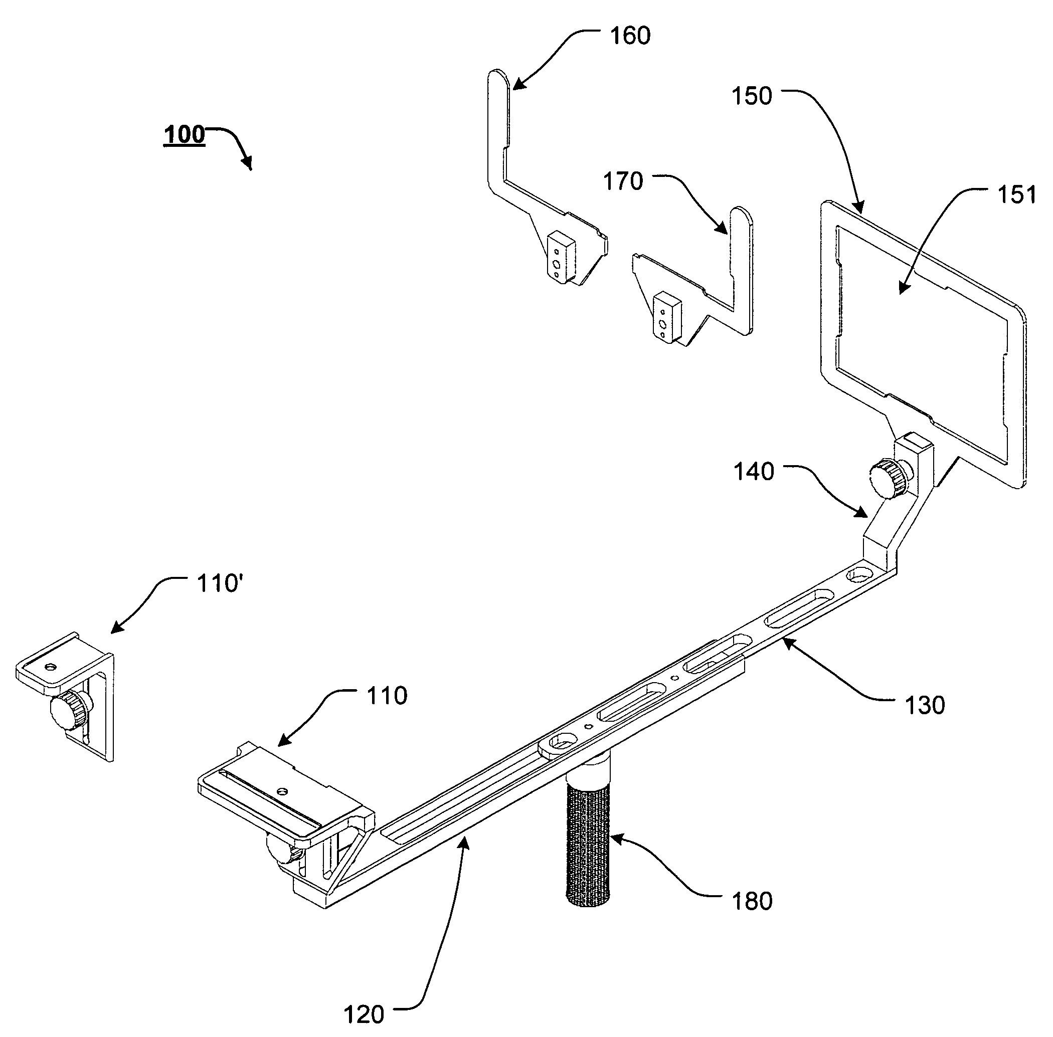
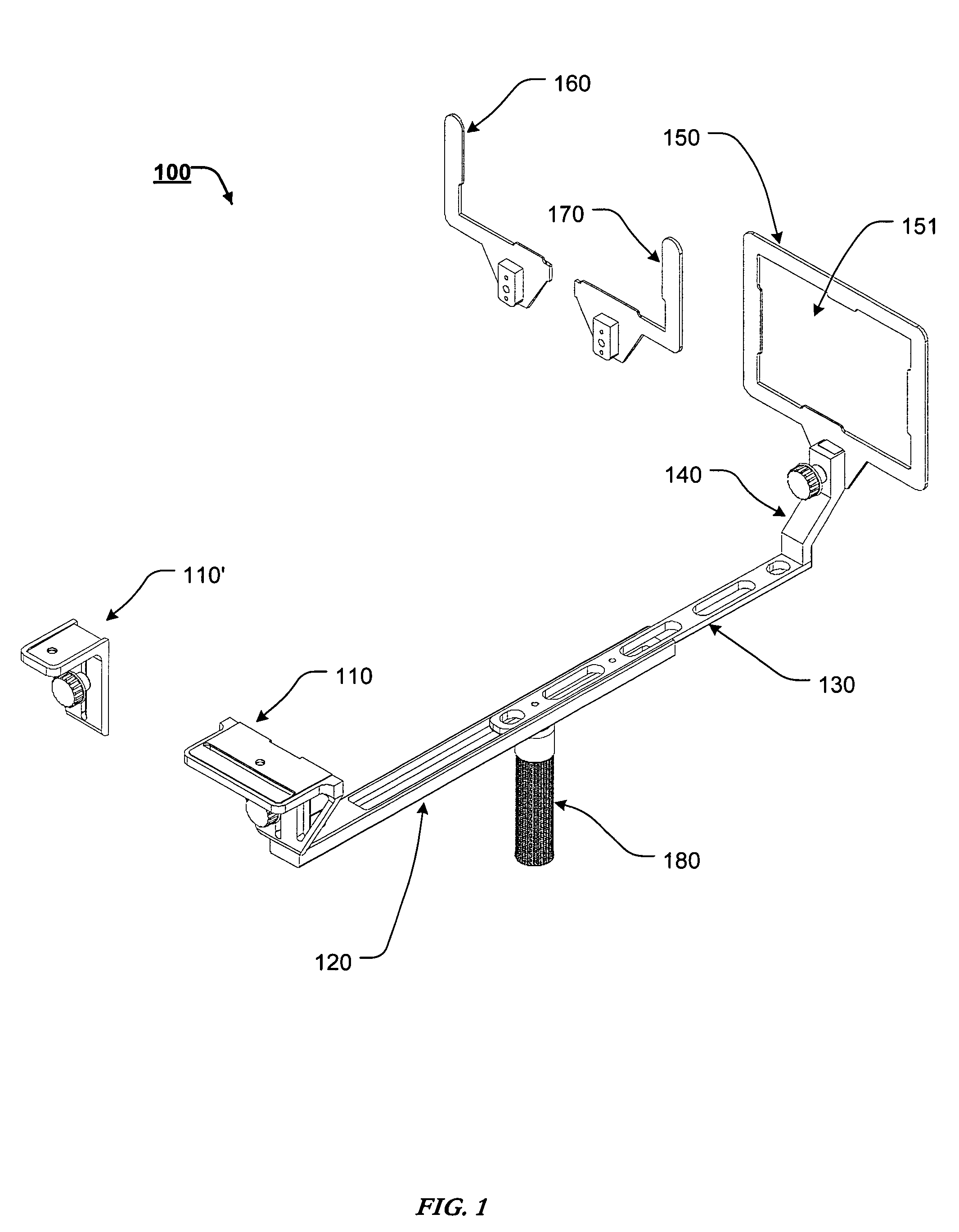
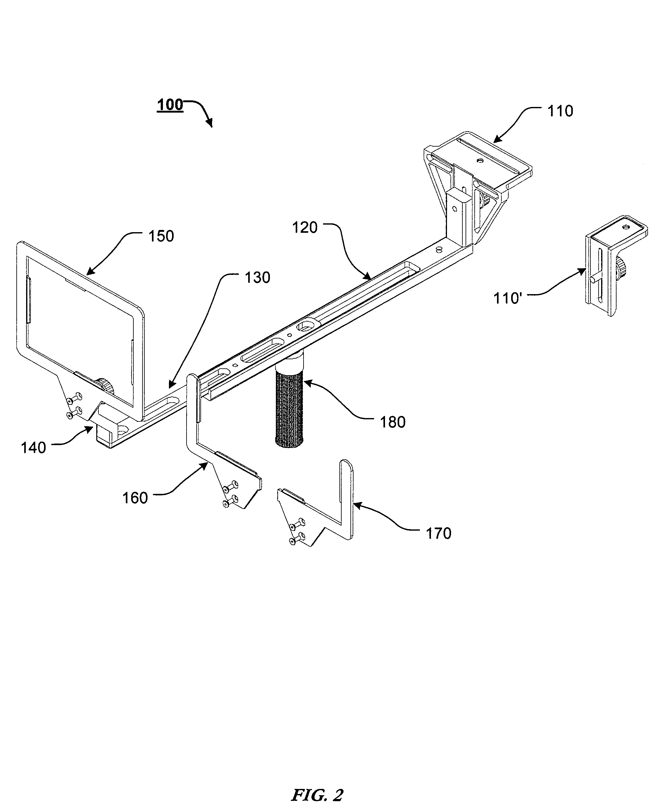
[0029]Accordingly, this invention provides a forensic photo frame, which reduces distortion in photogrammetry.
[0030]This invention separately provides a forensic photo frame, which reduces or eliminates the distortion associated with each of the four general types of distortion associated with the use of forensic scales.
[0031]This invention separately provides a forensic photo frame, which provides improved photographic accuracy and reliability, such that the resulting photographs are more valuable for any subsequent analysis.

Problems solved by technology

Improper orientation of the scale and camera, in relation to the item being photographed, may introduce distortion or inaccuracy.

Method used


Image

  • Device for reduction of angular distortion in photograpy
  • Device for reduction of angular distortion in photograpy
  • Device for reduction of angular distortion in photograpy

Examples


Embodiment Construction

[0043]For simplicity and clarification, the design factors and operating principles of the forensic photo frame of this invention are explained with reference to various exemplary embodiments of a forensic photo frame according to this invention. The basic explanation of the design factors and operating principles of the forensic photo frame is applicable for the understanding, design, and operation of the forensic photo frame of this invention.

[0044]The present invention is a device to reduce or eliminate photographic distortion associated with the use of forensic scales; accordingly, it is applicable to a broad range of photography. Any photographic image that requires correct perspective to a scale can benefit from the forensic photo frame of this invention. Evidentiary photography, however, is a clear example of a field where the need for accuracy is compelling because such photographs may be used for forensic photogrammetry in criminal or civil proceedings. For bitemark photogr...


PUM


Abstract

A camera mount, comprising a camera mounting portion, wherein a camera can be removably coupled to the camera mounting portion, such that a photographic plane of the camera is parallel to a photographic plane of the camera mounting portion; a rail portion, wherein the rail portion extends from the camera mounting portion substantially perpendicular to the photographic plane of the camera mounting portion; and a frame, wherein the frame is adapted to receive one or more reference scales such that a photographic plane of the one or more reference scales is parallel to a photographic plane of the camera mounting portion, and wherein the frame is coupled to the rail portion such that a photographic plane of the frame is parallel to a photographic plane of the camera mounting portion elements.

Description

CROSS-REFERENCE TO RELATED APPLICATIONS[0001]This is a Continuation-In-Part of U.S. patent application Ser. No. 11 / 179,435, filed Jul. 12, 2005 now U.S. Pat. No. 7,452,142, which claims the benefit of U.S. Provisional Patent Application Ser. No. 60 / 654,143, filed Feb. 18, 2005, the disclosures of which are incorporated herein by reference.BACKGROUND OF THE INVENTION[0002]1. Field of the Invention[0003]The present invention relates to a device to reduce distortion in photogrammetry. More specifically, the present invention is drawn to a device that reduces or eliminates distortion in forensic photography.[0004]2. Description of Related Art[0005]Photogrammetry is the art or science of obtaining reliable measurements by means of photography. Some categories of photography may use a reference or object within the photographed field to give context to the object or location photographed. For example, in forensic photography of evidence, a physical reference scale aids in showing the size...

Claims


Application Information

Patent Timeline
IPC IPC(8): G03B17/00G01B13/02
CPCF16M11/046F16M11/2092G03B17/561G03B17/00F16M13/04
Inventor SMITH, ELIZABETH RUTH
Owner SMITH ELIZABETH RUTH
Learn More