Baler with automatic sensor calibration

a baler and sensor technology, applied in baling, picking devices, agricultural tools and machines, etc., can solve the problems of improper calibration of balers, inability to accurately calibrate, and inability to accurately measure the accuracy of balers

Active Publication Date: 2011-04-05
DEERE & CO
View PDF22 Cites 18 Cited by
  • Summary
  • Abstract
  • Description
  • Claims
  • Application Information

AI Technical Summary

Benefits of technology

[0009]It is thus an object of the present invention to provide a bale shape sensor that does not require a laborious calibration.
[0010]A baler is thus provided having a baling chamber. A sensor arrangement comprises at least one sensor for providing information about a mechanical property of a bale built in the baling chamber and a control unit receiving signals from the sensor. The control unit, during operation, automatically calibrates the signals from the sensor based upon at least one signal from the sensor that is or was received in at least one known state of the sensor. Here, calibrating means converting the sensor signal into a calibrated signal that is independent from mechanic and / or electric tolerances of the sensor and its mounting in the baler. Thus, the control unit can derive an offset and / or a conversion factor for the sensor during the known state of the sensor and later apply one or both of them to the sensor signal. After all, a correct measurement value is derived from the sensor signal, without any necessity of a mechanical calibration of the sensor.
[0011]Dispensing with a mechanical sensor calibration avoids calibration elements for the sensor, allows mounting the sensor in areas of the baler that can be difficult to access, and reduces work and time during assembly of the baler and subsequent service work.
[0016]Analogously, the control unit can assume that the baling chamber is entirely filled—and thus the sensor is in its position corresponding to a completely filled baling chamber—when the sensor signal indicates, also considering a sufficiently long time allowing building (while driving on a sinusoidal path) and ejecting of at least one bale, a highest or maximum value. This maximum value allows deriving a conversion factor that is later multiplied with the sensor value, such that the final output value of the control unit is corresponding to a maximal value when the baling chamber is full.

Problems solved by technology

A disadvantage of the above-described electro-mechanical sensors for sensing the bale diameter, comprising mechanical feelers coupled to potentiometers, is that the mechanical connection between the feeler and the potentiometer is subject to tolerances.
The calibration is cumbersome and thus one can frequently find balers running with an improper calibration of the bale size sensors.

Method used


Image

  • Baler with automatic sensor calibration
  • Baler with automatic sensor calibration
  • Baler with automatic sensor calibration

Examples


Embodiment Construction

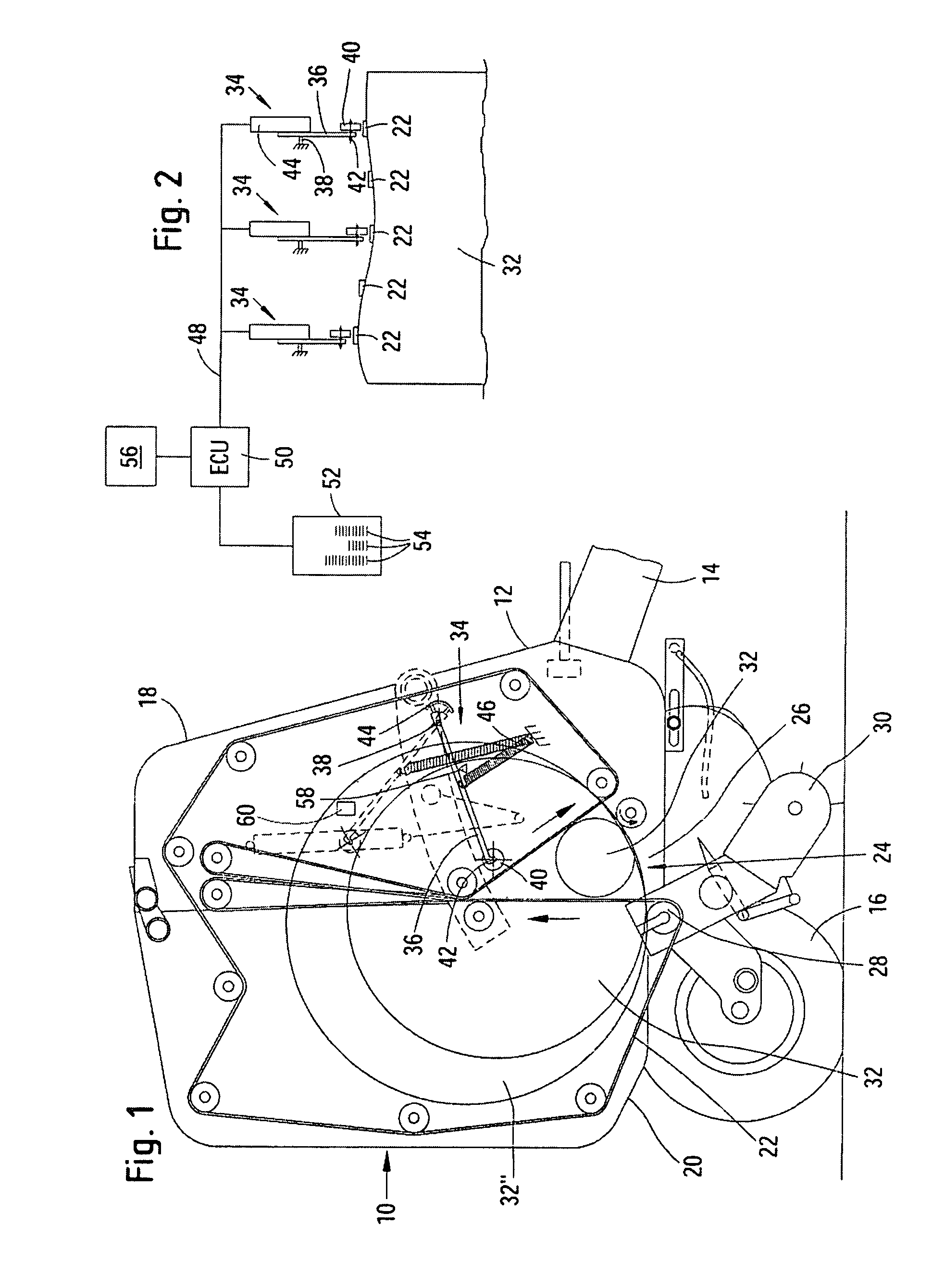
[0024]Referring now to the drawings, FIG. 1 shows a rotary baler 10 with a housing 12 coupled to an agricultural tractor, not shown, by means of a towbar 14, in order to be towed across a field to the right, in a direction of operation. The baler 10 is supported on wheels 16 and the housing 12 is composed of a rigid front housing half 18 and a pivoted rear housing half 20, which are connected to each other via an upper joint. The housing 12 carries a multitude of rolls or rollers. Several endless conveying elements 22, extending alongside each other, are carried over the rolls. The conveying elements 22 largely surround a baling chamber 24, together with side walls of the housing 12. In this embodiment, the conveying elements 22 are configured as belts but may be otherwise configured, for example as chains. An inlet 26 is provided in the lower region of the baling chamber 24. The inlet 26 is bordered to the rear by a roll 28 and permits the entry of crop taken up by a pick-up 30 int...


PUM


Abstract

A baler comprises a baling chamber and a sensor arrangement. The sensor arrangement comprises at least one sensor arranged to provide information about a mechanical property of a bale built in the baling chamber and a control unit receiving signals from the sensor. The control unit is operable to automatically calibrate the signals from the sensor based upon at least one signal from the sensor received in at least one known state of the sensor.

Description

FIELD OF THE DISCLOSURE[0001]The disclosure relates to an agricultural baler comprising a baling chamber and a sensor arrangement with at least one sensor arranged to provide information about a mechanical property of a bale built in the baling chamber and a control unit receiving signals from the sensor.BACKGROUND OF THE DISCLOSURE[0002]A tractor / baler combination is used in agriculture to take up crop lying in a swath on a field with a pick-up and to press and bind the crop into a bale in a baling chamber. Due to different widths of the baling chamber and the swath, it is appropriate to steer the tractor in a manner such that the pick-up of the baler is not continuously centered over the swath, but moves over time successively to the left and to the right side of the swath, in order to produce a cylindrical bale. Thus, sensors for the shape or deformability of the bale have been proposed that provide steering information to steered wheels of the baler (U.S. Pat. No. 4,702,066 A) o...

Claims


Application Information

Patent Timeline
Patent Type & Authority Patents(United States)
IPC IPC(8): B30B15/26A01D39/00
CPCA01F15/0833A01F2015/076
Inventor VIAUD, JEAN
Owner DEERE & CO
Why Eureka
Try Eureka